Single-side current detection device and method based on magnetoresistive effect sensor array

A technology of sensor array and magnetoresistive effect, which is applied in the direction of measuring devices, voltage/current isolation, instruments, etc., can solve the problems of difficulty in achieving accuracy and cost, large influence of spatial arrangement errors, inaccurate positioning, etc., and reduce the amount of calculation , maximize efficiency, and simplify the positioning steps

Active Publication Date: 2021-08-31
芯曜途科技(珠海)有限公司
View PDF12 Cites 2 Cited by
  • Summary
  • Abstract
  • Description
  • Claims
  • Application Information

AI Technical Summary

Problems solved by technology

[0004] The disadvantage of current monitoring devices based on magnetoresistive sensing modules is that, on the one hand, it is still impossible to get rid of the design of placing the current-carrying conductor in the middle of the device, so there is still room for improvement in installation convenience. On the one hand, when using the array method for measurement, The pursuit of precision requires the use of a large number of single-axis or multi-axis magnetoresistive sensors, while the pursuit of low cost has the problem of inaccurate positioning and the influence of space layout errors, making it difficult to achieve a balance between precision and cost. compromise

Method used


Image

  • Single-side current detection device and method based on magnetoresistive effect sensor array
  • Single-side current detection device and method based on magnetoresistive effect sensor array
  • Single-side current detection device and method based on magnetoresistive effect sensor array

Examples


Embodiment Construction

[0039] Embodiments of the present invention are described in detail below, examples of which are shown in the drawings, wherein the same or similar reference numerals designate the same or similar elements or elements having the same or similar functions throughout. The embodiments described below by referring to the figures are exemplary and are intended to explain the present invention and should not be construed as limiting the present invention.

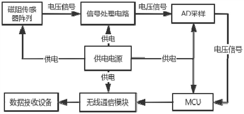
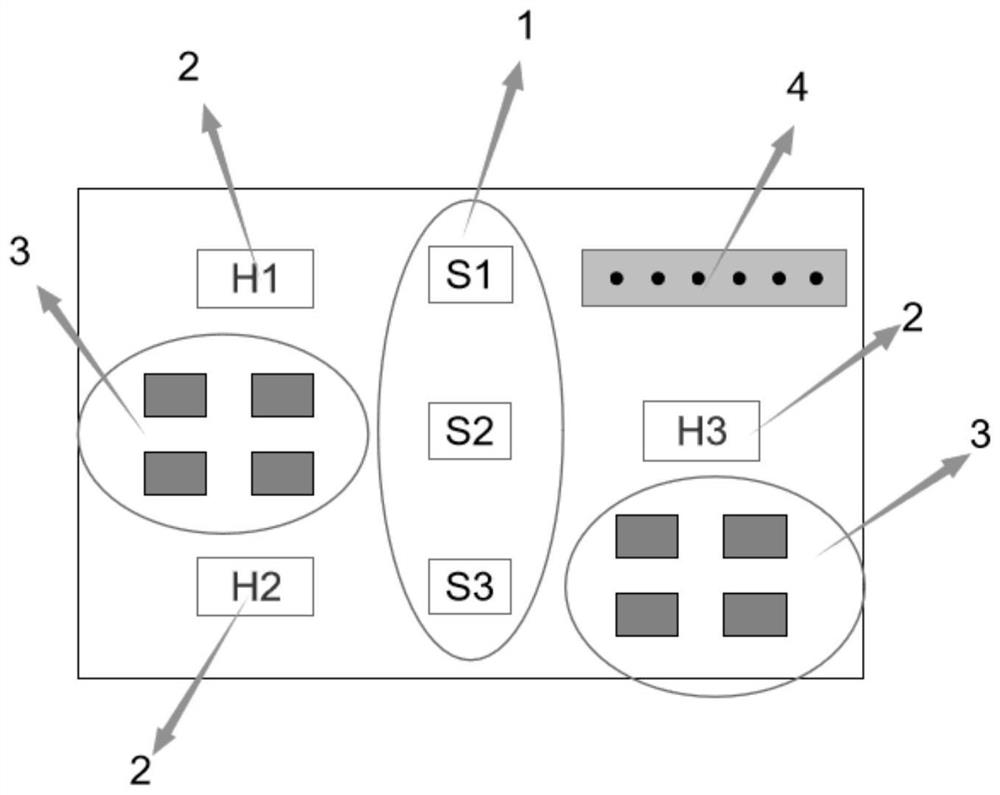
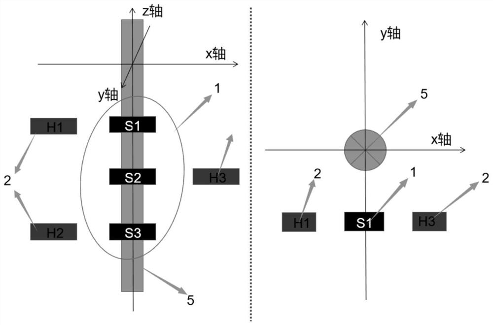
[0040] Such as figure 1 , 2 , 3 shows a preferred implementation of the unilateral current detection device based on the magnetoresistance effect sensor array in the present invention, the unilateral current detection device based on the magnetoresistance effect sensor array is a biaxial The current sensor device of the anisotropic magnetoresistance sensor and the uniaxial tunnel magnetoresistance sensor comprises a TMR magnetoresistance chip array, an AMR magnetoresistance chip array, a signal processing circuit module 3, a wir...


PUM


Abstract

The invention provides a single-side current detection device and method based on a magnetoresistance effect sensor array. The single-side current detection device comprises a TMR magnetoresistance chip array, an AMR magnetoresistance chip array, a signal processing circuit module and a microcontroller. The TMR magnetoresistance chip array comprises three TMR magnetoresistance chips, the AMR magnetoresistance chip array comprises three AMR magnetoresistance chips, the TMR magnetoresistance chip array and the AMR magnetoresistance chip array measure a magnetic field around a current-carrying conductor and output a voltage signal, the voltage signal is processed by the signal processing circuit module and then input into the microcontroller, and the microcontroller calculates to obtain a current value of the current-carrying conductor to be measured. The high-sensitivity current measuring device which has a wire positioning function and can perform wire current value non-contact measurement on the single side of a wire is manufactured based on the magnetoresistive effect principle, the use scenes are numerous, a telescopic rod can be arranged to detect the wire current in the distance, and the device can be fixedly installed and used for monitoring the current of a power transmission line. Or the device is carried on an unmanned aerial vehicle or a robot for circuit inspection testing and the like.

Description

technical field [0001] The invention belongs to the field of electrical technology and grid current measurement science, and relates to a non-contact current measuring device and method including an anisotropic magnetoresistance sensor array and a tunneling magnetoresistance sensor array. Background technique [0002] The real-time monitoring of the smart grid has always relied on advanced measurement methods and sensing technologies. In the new era of intelligent grid construction, in order to innovate the defects of traditional technologies, the development of circuit testing equipment must meet the requirements of high efficiency, convenience, small size and safety. At present, the current detection of transmission lines generally adopts contact and non-contact measurement methods. Most of the current transformers used in the domestic power grid are based on the principle of electromagnetic induction. This kind of device needs to be manually contacted on-site. Type detect...

Claims


Application Information

Patent Timeline
Patent Type & Authority Applications(China)
IPC IPC(8): G01R19/25G01R15/20
CPCG01R19/25G01R15/205
Inventor 葛道晗王浩文张立强李伟杨平
Owner 芯曜途科技(珠海)有限公司
Why Eureka
Try Eureka