Check patentability & draft patents in minutes with Patsnap Eureka AI!

Visual inertial navigation method, device and apparatus and computer readable storage medium

A vision and difference calculation technology, applied in the field of inertial navigation, can solve the problems of low calculation efficiency, poor calculation accuracy and stability, etc.

Pending Publication Date: 2021-08-31
JUXING TECH SHENZHEN CO LTD
View PDF0 Cites 3 Cited by
  • Summary
  • Abstract
  • Description
  • Claims
  • Application Information

AI Technical Summary

Problems solved by technology

[0007] In order to solve the technical defects of poor accuracy and stability and low calculation efficiency of the visual inertial navigation odometer in the prior art, the present invention proposes a visual inertial navigation method, device, equipment and computer-readable storage medium

Method used


Image

  • Visual inertial navigation method, device and apparatus and computer readable storage medium
  • Visual inertial navigation method, device and apparatus and computer readable storage medium
  • Visual inertial navigation method, device and apparatus and computer readable storage medium

Examples


Embodiment 1

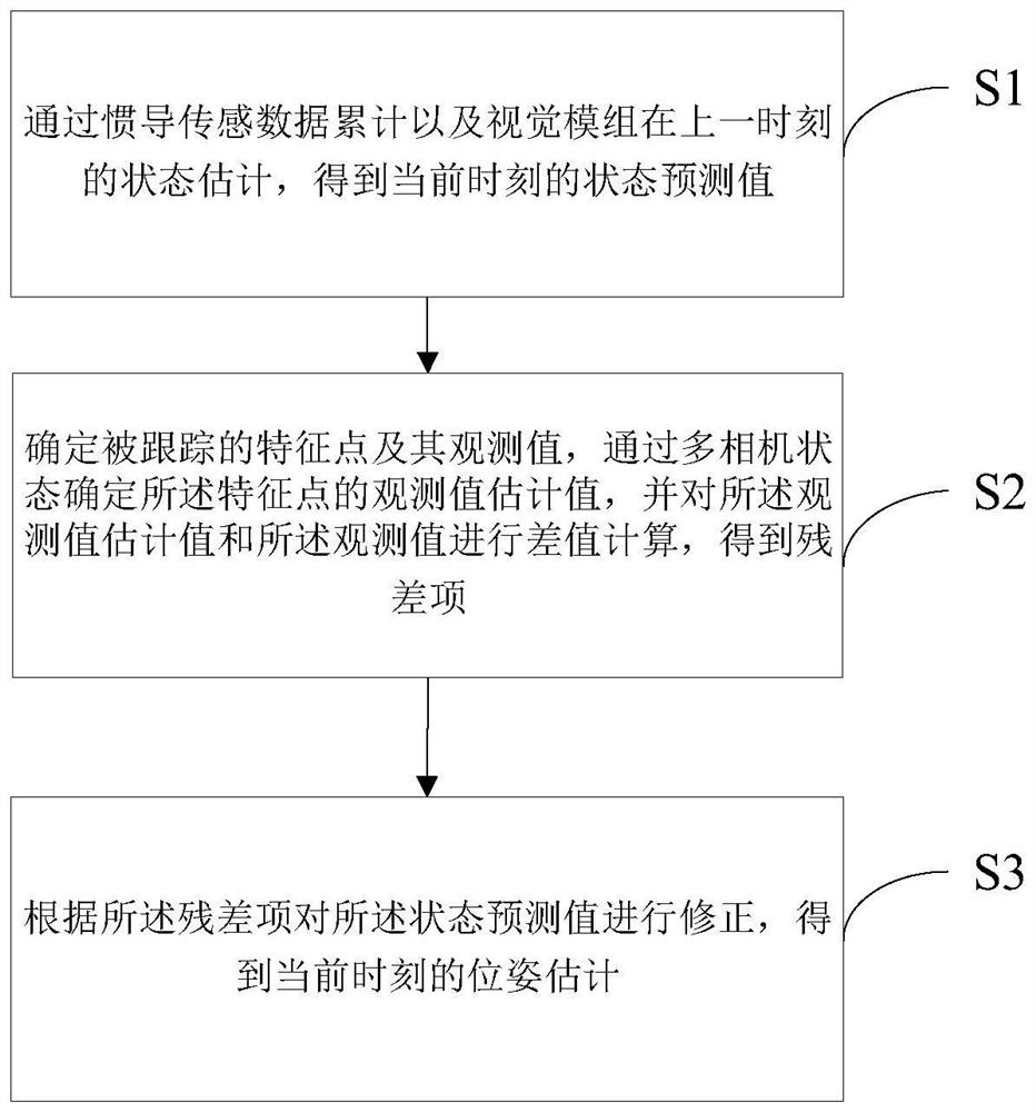
[0031] figure 1 It is the first flow chart of the visual inertial navigation method provided by the embodiment of the present invention. This embodiment proposes a visual inertial navigation method, which includes:

[0032] S1. Obtain the state prediction value at the current moment through the accumulation of inertial navigation sensor data and the state estimation of the vision module at the previous moment;

[0033] S2. Determine the tracked feature point and its observation value, determine the estimated value of the observed value of the feature point through the multi-camera state, and calculate the difference between the estimated value of the observed value and the observed value, and obtain the residual item ;

[0034] S3. Correct the predicted state value according to the residual term to obtain the pose estimation at the current moment.

[0035] In this embodiment, firstly, the pose of the vision module is predicted from the previous moment to the current state b...

Embodiment 2

[0040] figure 2It is the second flowchart of the visual inertial navigation method provided by the embodiment of the present invention. Based on the above-mentioned embodiments, the state prediction value at the current moment is obtained through the accumulation of inertial navigation sensor data and the state estimation of the vision module at the previous moment, including:

[0041] S11. During the time period from the previous moment to the current moment, accumulate the acceleration count value and the angular velocity count value in the inertial navigation sensor data, and at the same time, combine the state estimation of the vision module at the last moment, Obtain the state prediction value.

[0042] In this embodiment, when the required RGB image or grayscale image combined with the depth image is acquired according to the preset image acquisition frequency, since the frequency of acquiring inertial navigation sensor data by the inertial navigation component is high...

Embodiment 3

[0053] image 3 It is the third flow chart of the visual inertial navigation method provided by the embodiment of the present invention. Based on the above embodiments, the tracked feature points and their observed values ​​are determined, the estimated observed values ​​of the feature points are determined through the multi-camera state, and the difference between the estimated observed values ​​and the observed values ​​is calculated to obtain residuals, including:

[0054] S21. Perform feature extraction and matching according to the RGB image or grayscale image acquired by the vision module, to obtain tracked feature points and their observed values.

[0055] In this embodiment, after the initialization is completed, firstly, the corresponding RGB image or grayscale image is obtained through the visual module, and then, according to the current positioning requirements and corresponding parameter configuration, relevant feature extraction and matching operations are perfo...


PUM


Abstract

The invention discloses a visual inertial navigation method, device and apparatus and a computer readable storage medium. The method comprises the following steps of obtaining a state prediction value at a current moment through the inertial navigation sensing data accumulation and the state estimation of a visual module at a previous moment; determining a tracked feature point and an observed value thereof, determining an estimated value of the observed value of the feature point through a multi-camera state, and performing difference calculation on the estimated value of the observed value and the observed value to obtain a residual term; and correcting the state prediction value according to the residual term to obtain the pose estimation at the current moment. According to the invention, a visual inertial navigation odometer scheme fusing depth information is realized, the accuracy of an odometer is improved, the stability of the odometer in a weak illumination or weak texture environment is enhanced, and meanwhile, the system overhead is saved.

Description

technical field [0001] The present invention relates to the technical field of inertial navigation, in particular to a visual inertial navigation method, device, equipment and computer-readable storage medium. Background technique [0002] In the prior art, VIO (Visual Inertial Odometry, Visual Inertial Odometry) refers to an algorithm that uses data from a visual sensor (camera) and an inertial navigation sensor (IMU, Inertial measurement unit) to estimate the current pose of a system body. This algorithm has important applications in autonomous mobile vision modules, unmanned vehicles, drone positioning and navigation, AR (Augmented Reality, augmented reality), etc. As an effective sensor for the relative positioning of the mobile vision module, the visual inertial odometry provides real-time pose information for the vision module. Compared with pure visual odometry, visual inertial odometry has the following advantages: [0003] 1. The absolute scale can be estimated th...

Claims


Application Information

Patent Timeline
IPC IPC(8): G06T7/246G06T7/521G06T7/73G01C21/16
CPCG01C21/16G06T7/246G06T7/521G06T7/73
Inventor 陈鸿健刘俊斌
Owner JUXING TECH SHENZHEN CO LTD
Features
  • R&D
  • Intellectual Property
  • Life Sciences
  • Materials
  • Tech Scout
  • Unparalleled Data Quality
  • Higher Quality Content
  • 60% Fewer Hallucinations
Learn More