Method for increasing interlayer binding force of high-temperature superconducting narrow-headed wire

A technology of interlayer bonding and high-temperature superconductivity, which is applied in the usage of superconductor elements, superconducting devices, superconducting/high-conducting conductors, etc., can solve the problem of inconspicuous effect, insufficient bonding force, and inability to satisfy lateral twisting and other problems, to achieve the effect of reducing the possibility of quenching, increasing production costs, and high toughness

Active Publication Date: 2021-08-31
SHANGHAI JIAO TONG UNIV
View PDF10 Cites 1 Cited by
  • Summary
  • Abstract
  • Description
  • Claims
  • Application Information

AI Technical Summary

Problems solved by technology

The metal-sheathed high-temperature superconducting wire obtained by the preparation method is twisted and the internal strips are tightly bonded without deformation, and the ratio of its critical current to the critical current of the superconducting wire before armoring is higher than 95%, which solves the existing problem The superconducting strips of superconducting wires cannot meet the technical problem of lateral twisting due to insufficient stacking bonding force; however, this patent describes the process of using metal-clad superconducting stacked wires to achieve enhanced bonding force. The width of the superconducting tape varies from 40mm to 100mm; because it requires an additional metal sheath, the effect is not obvious for the narrower width of the superconducting tape

Method used


Image

  • Method for increasing interlayer binding force of high-temperature superconducting narrow-headed wire
  • Method for increasing interlayer binding force of high-temperature superconducting narrow-headed wire
  • Method for increasing interlayer binding force of high-temperature superconducting narrow-headed wire

Examples


Embodiment 1

[0042] For 4 second-generation high-temperature superconducting strips 2 with a width of 2mm and a length of 30mm and 2 copper strips 1 with a width of 2mm and a length of 30mm, prepare a high-temperature superconducting narrow stack containing "soldering tin columns" according to the following steps Wire:

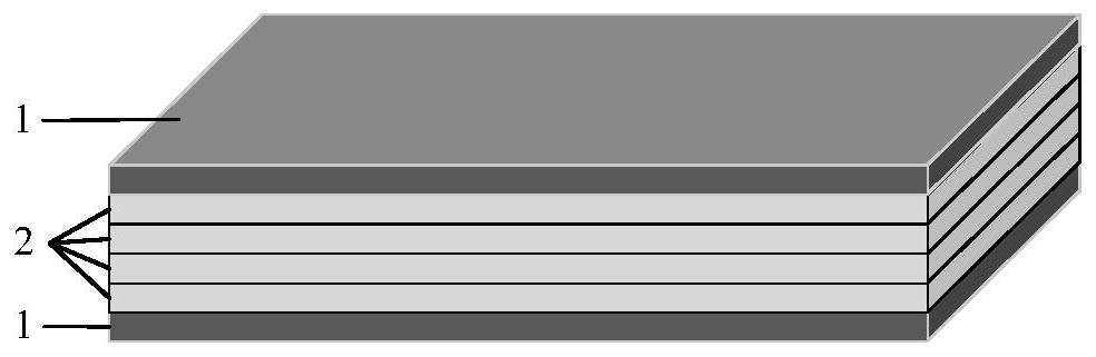
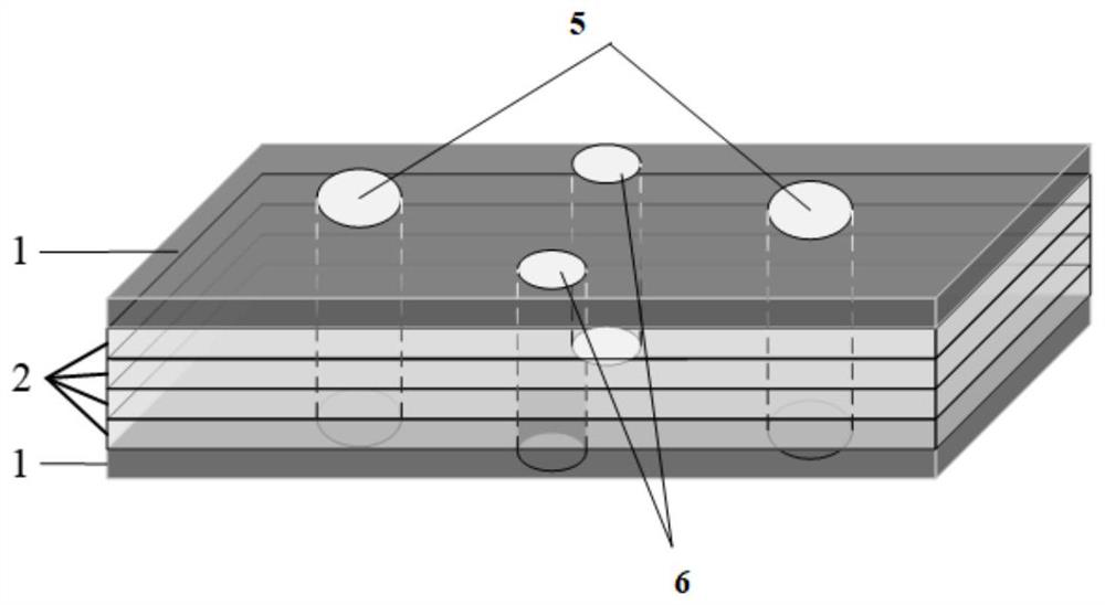
[0043] (1) The second-generation high-temperature superconducting strip 2 and the copper strip 1 are stacked and packaged into a high-temperature superconducting narrow stack line after being tinned in a tin furnace; figure 1 It is a schematic diagram of a high-temperature superconducting narrow stack line, wherein the second-generation high-temperature superconducting strip 2 is located between the copper strips 1 and 1 .

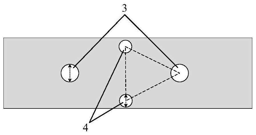
[0044] (2) Make circular through holes through all layers on the surface of the narrow pile line, and the through holes are divided into the first through hole 3 (9 pieces) and the second through hole 4 (16 pieces). figure 2 It is a top view of the h...

Embodiment 2

[0059] For 4 second-generation high-temperature superconducting strips 2 with a width of 2mm and a length of 30mm and 2 copper strips 1 with a width of 2mm and a length of 30mm, prepare a high-temperature superconducting narrow stack containing "soldering tin columns" according to the following steps Wire:

[0060] (1) The second-generation high-temperature superconducting strip 2 and the copper strip 1 are stacked and packaged into a high-temperature superconducting narrow stack line after being tinned in a tin furnace;

[0061] (2) Make circular through holes through all layers on the surface of the narrow pile line, and the through holes are divided into the first through hole 3 (9) and the second through hole 4 (16), and the first through hole 3 has an aperture of 0.5 mm; the diameter of the second through hole 4 is 0.2mm. The second through hole is located on the perpendicular bisector of the connecting line of two adjacent first through holes, and the second through hol...

Embodiment 3

[0067] The present embodiment is the same as the embodiment, and the difference is only that: the first through hole 3 aperture is 0.44mm (22% of the strip width); the second through hole 4 aperture is 0.36mm (18% of the strip width). ).

[0068] The performance test result of this embodiment is as follows:

[0069] table 3

[0070]


PUM


Abstract

The invention relates to a method for increasing the interlayer binding force of a superconducting narrow headed wire. The method comprises the following steps: S1, stacking a superconducting strip and other metal strips which are equal in width, and then tinning and packaging the stacked superconducting strip and other metal strips into a high-temperature superconducting narrow headed wire through a tinning furnace; S2, punching holes in the surface of the narrow-headed wire obtained in the step S1, wherein the holes are through holes; S3, re-packaging the through holes of the narrow pile lines obtained in the step S2. According to the invention, a tin-plated packaging mode is adopted after the narrow headed wire is punched, and a'soldering tin column 'is formed by penetrating through all upper and lower layers of the narrow headed wire, so the weight and the size of the narrow headed wire are not influenced, the manufacturing cost is not greatly increased, and the feasibility is provided for practical engineering application; in mechanical operations of twisting, bending and the like, compared with a metal sheath, the soldering tin column is smaller in size, higher in toughness and capable of better meeting application requirements under working conditions.

Description

technical field [0001] The invention belongs to the technical field of superconducting technology, and in particular relates to a method for increasing the binding force between layers of high-temperature superconducting narrow stack wires. Background technique [0002] Since the discovery of high-temperature superconducting tape, its development and production have achieved remarkable results. At present, its mass production has been basically realized. Although the high-temperature superconducting tape has a current-carrying capacity far exceeding that of conventional conductors, the preparation of a single high-temperature superconducting wire still requires the combination of multiple high-temperature superconducting tapes by stacking to achieve better carrying capacity. flow capacity and higher physical strength. [0003] Therefore, in order to meet the above requirements, the "high-temperature superconducting narrow stack line" realizes stacking multiple superconduct...

Claims


Application Information

Patent Timeline
Patent Type & Authority Applications(China)
IPC IPC(8): H01B12/16
CPCH01B12/16Y02E40/60
Inventor 李柱永钱刚金之俭洪智勇
Owner SHANGHAI JIAO TONG UNIV
Why Eureka
Try Eureka