Supercharge Your Innovation With Domain-Expert AI Agents!

Preparation method of super-junction MOSFET

A one-sided, N-type technology, used in semiconductor/solid-state device manufacturing, semiconductor devices, electrical components, etc., can solve the problem that reverse recovery characteristics cannot meet the needs of superjunction MOSFETs, and achieve fast recovery characteristics and improve reverse recovery. Speed, effect of reducing total time

Active Publication Date: 2021-08-31
VANGUARD SEMICON CORP
View PDF8 Cites 0 Cited by
  • Summary
  • Abstract
  • Description
  • Claims
  • Application Information

AI Technical Summary

Problems solved by technology

However, the reverse recovery characteristics of existing super-junction MOSFETs cannot meet the needs of super-junction MOSFETs in some application fields.

Method used


Image

  • Preparation method of super-junction MOSFET
  • Preparation method of super-junction MOSFET
  • Preparation method of super-junction MOSFET

Examples


Embodiment Construction

[0045] The technical solutions in the embodiments of the present application will be clearly described below in conjunction with the accompanying drawings. In the case of no conflict, the following embodiments and their technical features can be combined with each other.

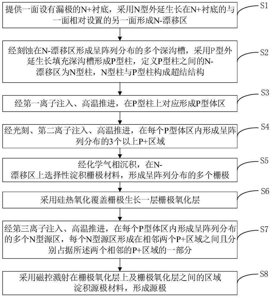
[0046] see image 3 , an embodiment of a method for manufacturing a super junction MOSFET provided by the present application, the method includes the following steps S1-S8.

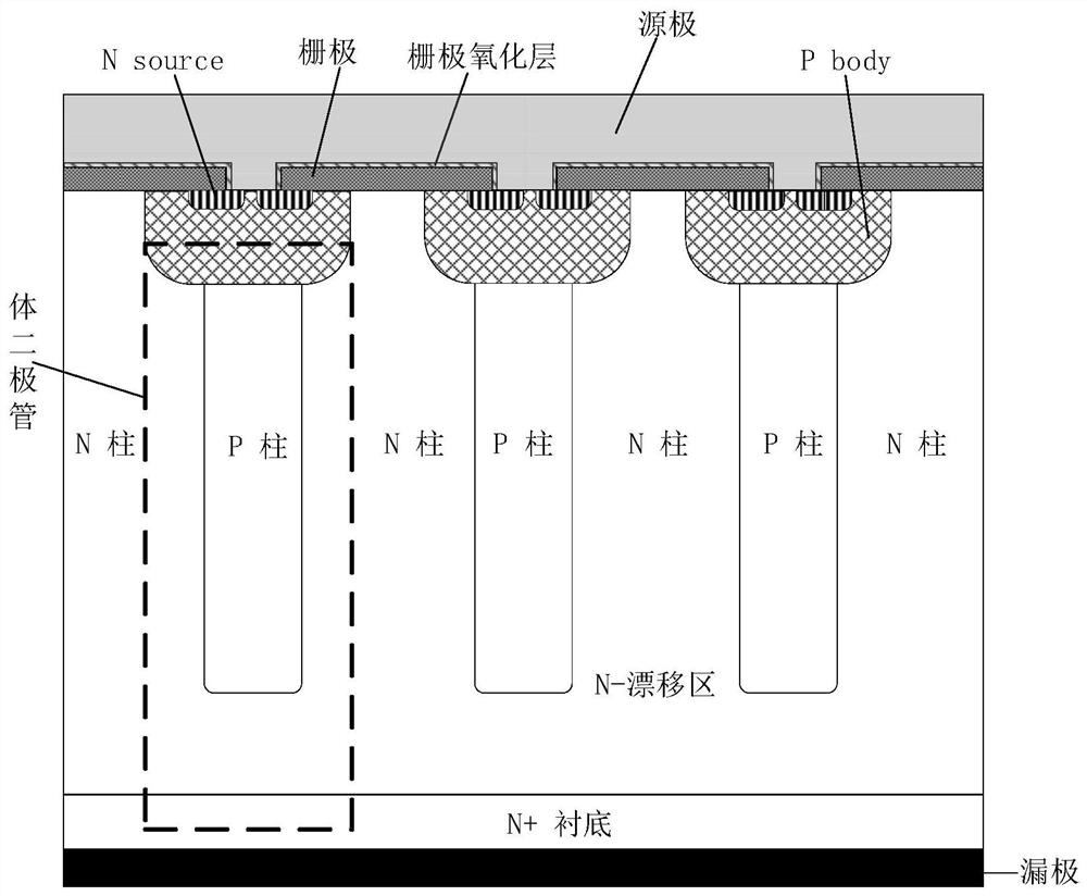
[0047] Please also refer to Figure 4 to Figure 10 , S1, providing an N+ substrate 2 with a drain 1 on one side 21, and forming an N-drift region 3 on the other side 22 of the N+ substrate 2 opposite to the one side 21 by N-type epitaxial growth.

[0048] S2. A plurality of deep trenches distributed in an array are formed in the N-drift region 3 after etching, and P-type epitaxial growth is used to fill the deep trenches to form P-type pillars 32 to define the N-drift region 3 between the P-type pillars 32 It is an N-type column 33 ,...


PUM


Abstract

The invention discloses a preparation method of a super-junction MOSFET, which comprises the following steps of forming a plurality of P-type body regions in an N-drift region, adopting a region which is limited by photoetching and is about to form more than three P+ regions, forming more than three P+ regions in each P-type body region through ion implantation and high-temperature propulsion. The injection efficiency of the anode of the body diode in the finally manufactured super-junction MOSFET can be reduced, the body diode takes the source electrode and the drain electrode of the super-junction MOSFET as the anode and the cathode respectively, the maximum reverse recovery current Irrm of the super-junction MOSFET can be reduced due to the reduction of the injection efficiency of the anode, the total time trr of the reverse recovery process is reduced, the reverse recovery speed is increased, the fast recovery characteristic of the super-junction MOSFET in the reverse recovery stage is increased, and the existence of the P+ region is beneficial to improving the avalanche tolerance of the device.

Description

technical field [0001] The present application relates to the technical field of semiconductor device manufacturing, in particular to a method for preparing a super junction MOSFET. Background technique [0002] The proposal of superjunction charge balance theory improves the trade-off relationship between breakdown voltage and on-resistance. see figure 1 Compared with the traditional MOSFET (Metal-Oxide-Semiconductor Field-Effect Transistor), the super junction MOSFET introduces alternately arranged N-type pillars and P-type pillars in the N-drift region. In this way, in the positive In the conduction stage, a lateral electric field can be formed between the P-type column and the N-type column, which is the so-called charge balance; however, the super-junction MOSFET is still a MOSFET in essence, and there is still a parasitic body diode (referred to as body diode) inside it. The source is the anode of the body diode and the drain is the cathode of the body diode. [000...

Claims


Application Information

Patent Timeline
IPC IPC(8): H01L21/336H01L29/06
CPCH01L29/66666H01L29/0634H01L29/0684
Inventor 赵浩宇雷秀芳姜春亮杜兆董李伟聪林泳浩
Owner VANGUARD SEMICON CORP
Features
  • R&D
  • Intellectual Property
  • Life Sciences
  • Materials
  • Tech Scout
  • Unparalleled Data Quality
  • Higher Quality Content
  • 60% Fewer Hallucinations
Learn More