
Multi-shovel plowing machine

A frame and crank technology, applied in the field of agricultural machinery and equipment, can solve problems such as unfavorable crop growth and development, unfavorable seed bed leveling, etc., and achieve the effects of favoring growth and development, reducing labor intensity and high efficiency

Active Publication Date: 2021-09-03
山东思代尔农业装备有限公司
View PDF8 Cites 1 Cited by
  • Summary
  • Abstract
  • Description
  • Claims
  • Application Information

AI Technical Summary

Problems solved by technology

However, when the common multi-shared plow plows the ground, because the soil is guided by the curved surface of the plow body, the soil in the entire plow depth is basically turned over, that is, the fertile and nutrient-rich mellow soil layer on the soil surface is turned over. At the bottom, the bottom layer of hard soil is turned over to the top, so it is not conducive to the growth and development of crops
In addition, when the common multi-share plow is used to plow the ground, commercial ridges and commercial trenches will be formed, which is not conducive to the leveling of the seedbed before sowing of crops.
With the emergence of hydraulic reversing plows in recent years, the problem of commercial ridges and commercial trenches formed when plowing the ground has been solved, but it still cannot solve the problem that the overall inversion of the soil within the entire plow depth is not conducive to the growth and development of crops.

Method used


Image

  • Multi-shovel plowing machine
  • Multi-shovel plowing machine
  • Multi-shovel plowing machine

Examples


Embodiment Construction

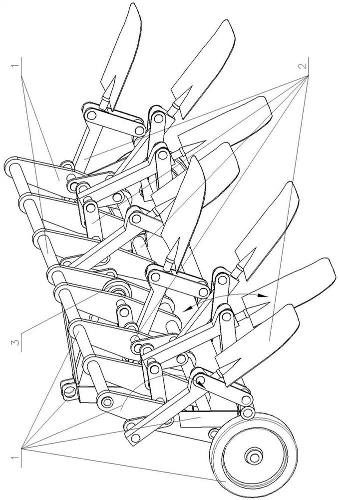
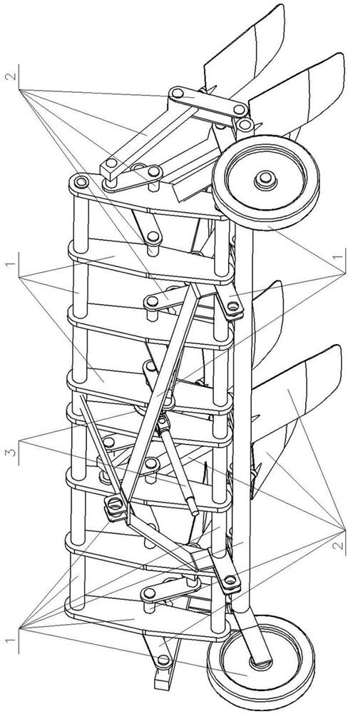
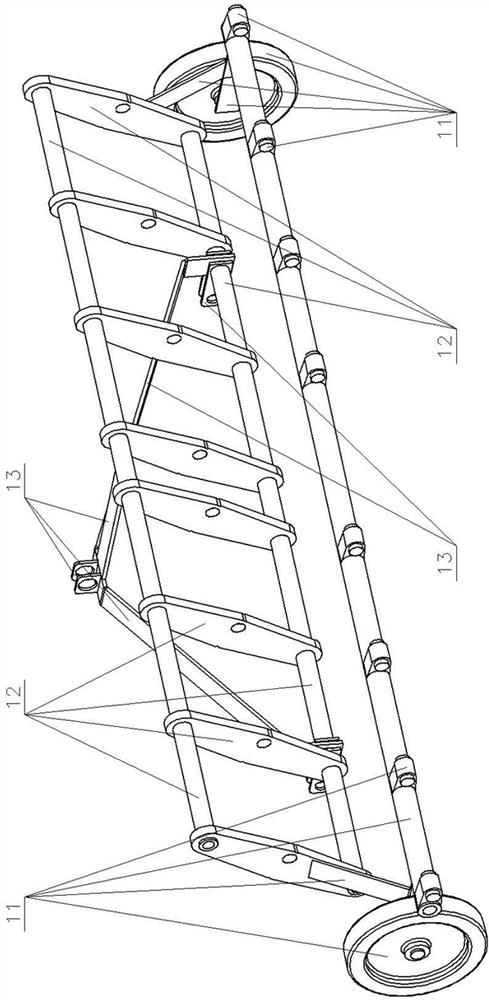
[0035] 1. Rack 11, bracket 111, support arm 112, beam 113, lug I 114, pin shaft I 115, support member 1151, outrigger I 1152, pin shaft II 1153, ground wheel 1154, outrigger II 1155, outrigger 12 , driving frame 121, link rod 122, driving plate 13, traction frame 131, herringbone frame 132, traction rod 133, lug II 134, lug III 2, turning mechanism 21, crankshaft 211, crank 212, center shaft Ⅰ 213, central shaft Ⅱ 214, drive shaft Ⅰ 215, drive shaft Ⅱ 22, rocker arm 221, rocker arm plate 23, ground turning shovel 231, connecting rod 232, spade handle 233, lug Ⅳ 234, symmetrical spade head 235, Left partial spade head 236, right partial spade head 3, driving device 31, speed reducer 32, universal joint 33, transmission shaft.

[0036] exist Figure 1-Figure 15 and Figure 17 In the shown embodiment: the support arms 111 of the support 11 of the frame 1 are in the shape of straight rods, and one ends of the two support arms 111 are symmetrically fixed on the two ends of the ho...


PUM


Abstract

The invention provides a multi-shovel plowing machine which is characterized in that support arms are fixed at two ends of a cross beam of a rack, a support part is mounted at the joint, n convex parts extend out of one side of the cross beam and are provided with convex lugs I of pin shafts I, a driving frame is fixed between the two support arms through two driving plates at two ends, and the tail ends of two legs of a propeller strut of a traction frame are mounted on the driving frame; a crankshaft of a plowing mechanism is composed of a center shaft I, n middle center shafts II, n handle cranks, n driving piece driving shafts I and two driving shafts II, n swing piece rocker arms are hinged to pin shafts I of n protruding piece lugs I respectively, one end of an n rod piece connecting rod of a plowing shovel is hinged to the middle of the n driving piece driving shafts I and the two driving shafts II, the other end of the n rod piece connecting rod is hinged to the pin shafts I of the n swing piece rocker arms, each shovel head is mounted in a longitudinal round hole of the connecting rod through a shovel handle; and a speed reducer of the driving device is connected with the center shaft I, and an input shaft is connected with a transmission shaft through a universal joint. The multi-shovel plowing machine replaces manual work and is high in efficiency, and soil is balanced after plowing.

Description

technical field [0001] The invention provides a multi-shovel plowing machine, which belongs to the field of agricultural machinery equipment and is mainly used for plowing and loosening the soil before sowing. Background technique [0002] Before sowing various crops, it is generally necessary to plow the ground and loosen the soil to achieve the purpose of loosening the soil. Before the advent of agricultural machinery, especially for the poorest farmers who had no cattle available, they could only use the "manpower + shovel" plowing mode. During the process of plowing the ground with a shovel, manpower steps on the shovel and pushes the soil backward, so that the soil within the entire plowing depth, that is, the mellow soil layer on the soil surface and the raw soil layer deep in the soil are completely disrupted and mixed. , which not only achieves the purpose of loosening the soil, but also balances the fertility in the soil and creates good conditions for the growth o...

Claims


Application Information

Patent Timeline
Patent Type & Authority Applications(China)
IPC IPC(8): A01B35/08A01B35/20A01B35/26A01B35/30
CPCA01B35/08A01B35/26A01B35/20A01B35/30
Inventor 石明霞
Owner 山东思代尔农业装备有限公司
Learn More