Lubricating oil feeding equipment for electromechanical machining

A lubricating oil, electromechanical technology, applied in the field of lubricating oil feeding equipment, can solve the problems of waste of lubricating oil, polluting the working environment, low efficiency, etc., and achieve the effect of reducing trouble, reducing external spraying, and high efficiency

Active Publication Date: 2021-09-03
徐州骏畅机电科技有限公司
View PDF6 Cites 3 Cited by
  • Summary
  • Abstract
  • Description
  • Claims
  • Application Information

AI Technical Summary

Problems solved by technology

[0002] When the sheet is cold-pressed, the sheet is first immersed in a lubricating oil tank, so that the surface of the sheet blank is adhered to the lubricating oil, so that the lubricating oil forms an oil film on the surface of the sheet blank, and when the blank is cold-pressed, the lubricating oil reduces the scraping of the surface of the blank by the die. At the same time, it is convenient to take out the blank from the die after cold pressing, and by immersing the sheet blank in lubricating oil first, and then placing it on the cold pressing equipment for electromechanical processing, this process also requires the staff to first immerse the sheet in lubricating oil Medium, low efficiency, and it is easy to cause the waste of lubricating oil and pollute the working environment

Method used


Image

  • Lubricating oil feeding equipment for electromechanical machining
  • Lubricating oil feeding equipment for electromechanical machining
  • Lubricating oil feeding equipment for electromechanical machining

Examples


Embodiment 1

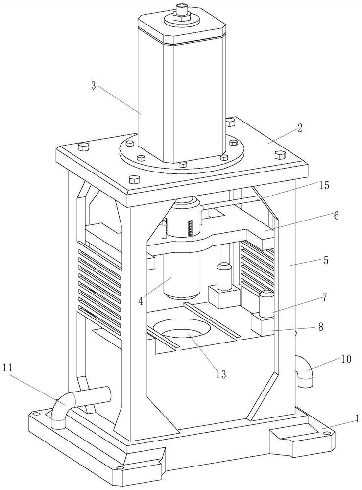
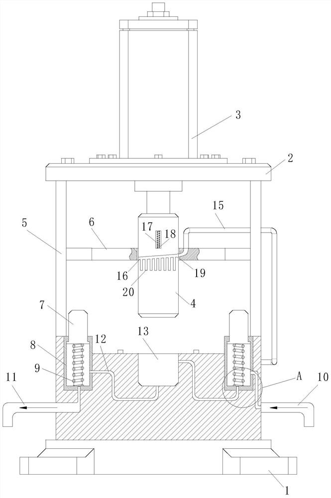
[0024] Refer Figure 1-5 , A lubricating oil charge device for electromechanical processing, including the bottom plate 1, the top plate 2, the cylinder 3, the cold press head 4, and the watering mechanism; the bottom plate 1 is fixed by the support rod 5, the top plate 2, the top plate 2 The piston column of the cylinder 3 is slid through the top plate 2 and the cold press 4 and the bottom plate 1 are mounted; the oil collecting machine includes a pressure plate 6, a piston rod 7, The piston cylinder 8, the pressure spring 9, the oil pipe 10, and the oil pipe 11; the intermediate position of the pressure plate 6 is disposed on the cold press 4, and the four corner positions of the pressure plate 6 are slidably connected to the side wall of the support rod 5. The piston cylinder 8 is mounted on one side of the support rod 5, and the inner portion of the piston cylinder 8 is slid in the piston rod 7, and one of the piston cylinders 8 in the bottom plate 1 is connected through the co...

Embodiment 2

[0034] Refer Figure 5 , Comparative Example 1. As another in the present invention, the four right angle positions on the bottom plate 1 open the fixing hole 23, and the equipment is fixed to the ground by the fixing hole 23, which is stabilized to ensure its operation stability. .

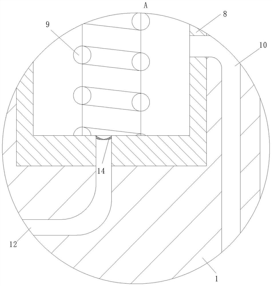
[0035] Working principle: First control the gas cylinder 3 without load, that is, the slot of the cold pressure groove 13 on the bottom plate 1 is not placed, the piston column of the cylinder 3 pushes the cold press head 4 to move in the cold pressure tank 13, and cold The push head 4 pushes the pressure plate 6 in the inner side wall of the support rod 5 toward the bottom plate 1, and the pressure plate 6 is pressed down the piston rod 7, the piston rod 7 pushes the reed spring 9, and then control the cylinder 3 to reset, the piston rod 7 is in the case 9 Under the elastic force, the piston rod 7 moves upward, and during the movement of the piston rod 7, since there is a rubber ring 14 in the cathet...


PUM


Abstract

The invention belongs to the technical field of electromechanical machining, and particularly relates to lubricating oil feeding equipment for electromechanical machining. The lubricating oil feeding equipment comprises a bottom plate, a top plate, an air cylinder, a cold pressing head and an oil feeding mechanism, wherein the oil feeding mechanism comprises a pressing plate, piston rods, piston cylinders, pressure springs, an oil inlet pipe and an oil outlet pipe; and the middle position of the pressing plate is arranged on the cold pressing head in a sleeving mode, the four corner positions of the pressing plate are slidably connected to the side walls of supporting rods, the piston cylinders are installed at one sides of the supporting rods, the interiors of the piston cylinders are slidably connected to the piston rods through the pressure springs, the middle position of one piston cylinder at one side of the bottom plate is communicated with the oil inlet pipe at one side of the bottom plate through a guide pipe, the bottom of the piston cylinder is communicated with a cold pressing groove of the bottom plate through a guide pipe, and a rubber ring for limiting the flowing direction of lubricating oil is arranged at the joint of the guide pipe and the piston cylinder.

Description

Technical field [0001] The present invention belongs to the technical field of electromechanical processing, and is specifically a lubricating oil tubing apparatus for electromechanical processing. Background technique [0002] When the sheet is cold pressure, the sheet is first immersed in the lubricating oil tank, so that the surface of the sheet blank is adhered to the surface of the sheet, so that the lubricant forms an oil film on the surface of the sheet material, when the blank is cold, the lubricating oil reduces the surface of the blank surface of the blank surface. The degree of injury, when the cold pressure is removed from the concave mode, and by immersing the sheet blank into the lubricant, it is placed on the electromechanical processing cold pressing device, and the process also needs the staff to first immerse the sheet to the lubricant In the middle, the efficiency is low, and it is easy to cause the lubricant's outer sprinkle waste, and pollute the working envi...

Claims


Application Information

Patent Timeline
Patent Type & Authority Applications(China)
IPC IPC(8): B21D37/18B21D22/02B21D37/10
CPCB21D37/18B21D22/02B21D37/10
Inventor 茌庚申
Owner 徐州骏畅机电科技有限公司
Why Eureka
Try Eureka