Reciprocating type uniform cut-off mechanism for aluminum alloy handrail production

A cutting mechanism, reciprocating technology, applied in shearing devices, metal processing equipment, accessories of shearing machines, etc., can solve the problems of low comprehensive cost, low cutting efficiency of railings, high working intensity, etc., to avoid cutting failure, The effect of increasing the use range and increasing the placement speed

Pending Publication Date: 2021-09-03
安徽佳之合新材料科技有限公司
0 Cites 0 Cited by

AI-Extracted Technical Summary

Problems solved by technology

[0002] Aluminum alloy railings are often used in building balcony railings, railings, stair railings, road guardrails, wall guardrails, lawn guardrails, etc., to play a protective role. The advantage of aluminum alloy railings is that they do not need to be painted and maintained, they are always new and not ...

Method used

Further in order to avoid cutting off the railing repeatedly, No. 1 plate 111 is provided with the drop 116 that runs through its surface, and the bottom of the drop 116 is provided with a corresponding arc plate 117, by being provided with drop 116, Placing the arc plate 117 is convenient for taking out the cut-off railing, avoiding cutting the cut-off railing multiple times.
Further in order to guarantee the cutting effect to railing, No. two reciprocating body 122 is provided with the No. two rotating groove 1262 that runs through its surface, and No. two rotating groove 1262 is circular piercing, and No. two rotating groove 1262 is provided with two No. 1 motor 1263, No. 2 motor 1263 passes through No. 2 rotating groove 1262 and is connected with No. 2 connector 1264, No. 2 connector 1264 is rotatably connected with No. 2 intermediate 1265, and No. 2 intermediate 1265 is rotatably connected with cutting knife 127. Cutting knife 127 is provided with No. 2 sliding body 1271, No. 2 sliding body 1271, drives cutting knife 127 to move by being provided with No. 2 motor 1263, can save human resources and guarantee the cutting effect to railing.
Further in order to improve the placement speed of railing, No. 1 plate 111 is provided with No. 1 sliding groove 118, and No. 1 sliding groove 118 is " concave " type structure groove, and connecting plate 128 is correspondingly provided with No. 3 sliding bodies 1281, No. 3 No. sliding body 1281 is slidingly connected with No. 1 sliding groove 118, and the No. 1 sliding groove 118 and No. 3 sliding body 1281 provided with sliding connection facilitate the disassembly and installation of connecting plate 128 and No. 1 plate 111, thereby improving the placement of railings. speed.
In addition, in order to avoid cutting failure, the cutting knife 127 is provided with an inserting rod 1272, and the No. 3 sliding body 1281 is provided with a fixing groove 1282 that runs through its surface, and the fixing groove 1282 is a circular opening, and the No. 1 plate 111 is correspondingly provided with Through the No. 1 fixed opening 119 on its surface, the No. 1 fixed opening 119 communicates with the No. 1 sliding groove 118,...

Abstract

The invention relates to the technical field of handrail production, in particular to a reciprocating type uniform cut-off mechanism for aluminum alloy handrail production. The reciprocating type uniform cut-off mechanism for aluminum alloy handrail production comprises a cut-off machine, and the cut-off machine at least comprises a mounting support and a power cutting body; the mounting support comprises a first plate, the first plate is connected with a second plate, supporting bodies are arranged at the bottom of the first plate and the bottom of the second plate, the second plate is provided with a first rotating groove, and the first plate is provided with first sliding bodies; and the power cutting body comprises a first reciprocating body, the first reciprocating body is connected with a second reciprocating body, the second reciprocating body is provided with a third sliding groove, the second reciprocating body is provided with a cut-off tool, the cut-off tool is provided with a second sliding body, the second reciprocating body is provided with a second sliding groove, the cut-off tool is provided with a handrail containing body, the handrail containing body comprises a connecting plate, the connecting plate is matched with a handrail fixing body in an inserted mode, and an adjusting body is arranged in the handrail fixing body. According to the handrail cut-off mechanism, the handrail cut-off efficiency is high, and the working intensity of workers is low.

Application Domain

Shearing machinesShearing machine accessories

Technology Topic

HandrailManufacturing engineering +3

Image

  • Reciprocating type uniform cut-off mechanism for aluminum alloy handrail production
  • Reciprocating type uniform cut-off mechanism for aluminum alloy handrail production
  • Reciprocating type uniform cut-off mechanism for aluminum alloy handrail production

Examples

  • Experimental program(2)

Example Embodiment

[0041] Example 1
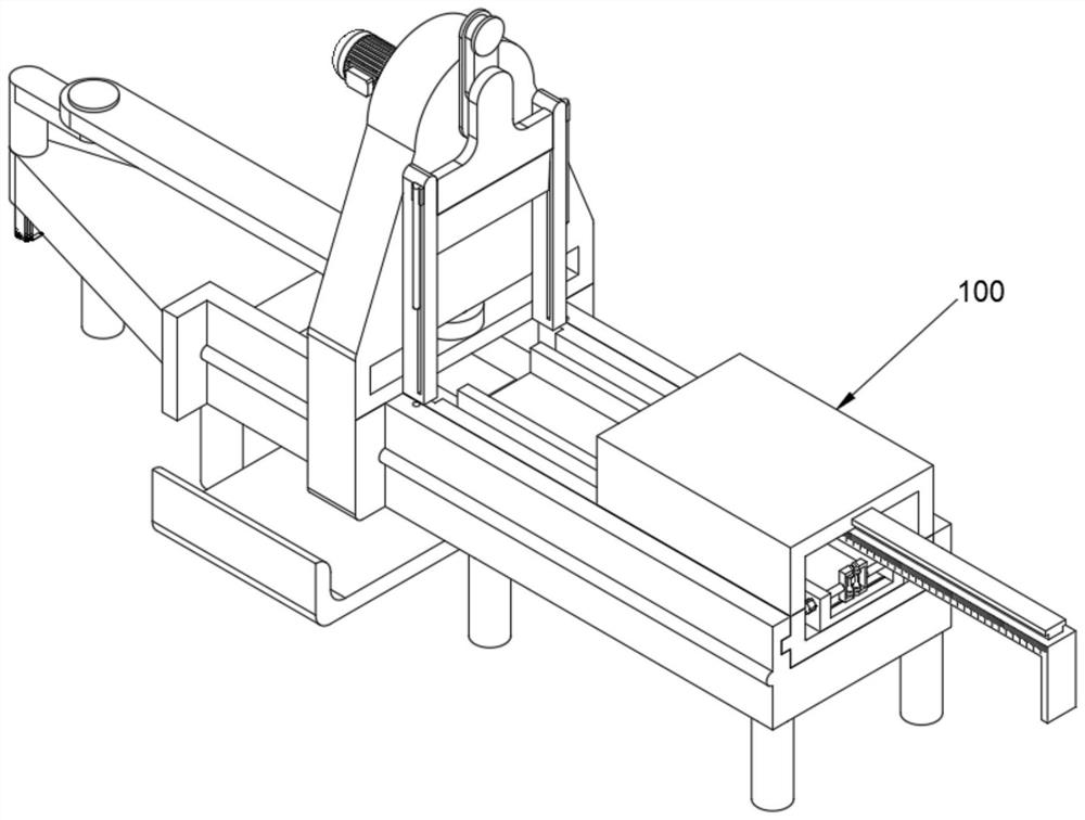
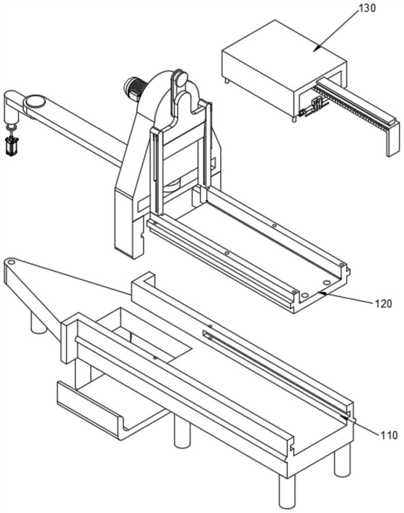
[0042] see Figure 1-Figure 8 As shown, the purpose of this embodiment is to provide a reciprocating-based uniform cutting mechanism for the production of aluminum alloy railings, including a cutting machine 100, and the cutting machine 100 includes at least:
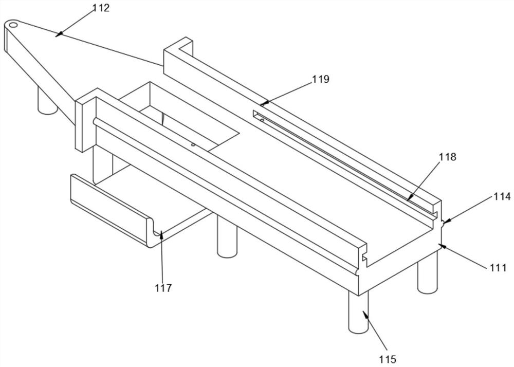
[0043] Mounting bracket 110, mounting bracket 110 includes No. 1 board 111, No. 1 board 111 is connected with No. 2 board 112, No. 1 board 111, No. The No. 1 rotating groove 113, the No. 1 rotating groove 113 is a "ten"-shaped cylindrical structure groove, the surface of the No. 1 plate 111 is correspondingly provided with a No. 1 sliding body 114, and the No. 1 sliding body 114 is a semi-cylindrical structure protrusion;
[0044]The power cutting body 120, the power cutting body 120 includes the No. 1 reciprocating body 121 located in the No. 1 rotating groove 113, the No. 1 reciprocating body 121 is connected with the No. 2 reciprocating body 122, and the bottom of the No. 2 reciprocating body 122 is provided with a No. 3 sliding groove 1267 , No. 3 sliding groove 1267 is a semi-cylindrical structure groove, No. 3 sliding groove 1267 is slidably connected with No. 1 sliding body 114, No. 2 reciprocating body 122 is provided with cutting knife 127, and cutting knife 127 is provided with No. 2 sliding body 1271, No. 2 reciprocating body 122 is provided with No. 2 sliding groove 1266, and No. 2 sliding body 1271 is slidably connected with No. 2 sliding groove 1266. The bottom of cutting knife 127 is provided with railing placement body 123, and railing placement body 123 includes the top of No. 1 plate 111. The connecting plate 128 is plugged with the railing fixed body 129 , and the railing fixed body 129 is provided with an adjusting body 130 .
[0045] In the specific use of this embodiment, after the adjusting body 130 to be cut off is fixed to the railing fixing body 129, the connecting plate 128 on which the railing fixing body 129 is installed is inserted into the No. 1 plate along the No. 1 sliding groove 118. In 111, No. 1 motor 124 drives No. 1 connecting body 125 to do circular motion with No. 1 rotating groove 113 as the center of circle, and rotates with No. 1 intermediate body 126 and No. 1 intermediate body 126 which is rotatably connected with No. 1 connecting body 125 The connected No. 1 rotating body 1261 drives the No. 2 reciprocating body 122 to move back and forth along the No. 1 sliding body 114. At the same time, the No. 2 motor 1263 drives the No. 2 connecting body 1264 to make a circular motion with the No. 2 rotating groove 1262 as the center of the circle. The No. 2 intermediate body 1265 which is rotatably connected with the No. 2 connecting body 1264 and the cutting knife 127 which is rotatably connected with the No. 2 rotating groove 1262 drive the cutting knife 127 to move up and down in the No. 2 sliding groove 1266. When the cutting knife 127 When it is located at a low place, it contacts with the railing and cuts off the railing, and the cut railing falls into the placement arc plate 117 from the drop opening 116 under the action of its own gravity.
[0046] Further, in order to avoid multiple cuts on the cut-off railing, No. 1 plate 111 is provided with a drop opening 116 that runs through its surface, and the bottom of the drop opening 116 is correspondingly provided with a placement arc plate 117. 117 is convenient for taking out the cut-off railing, and avoids cutting the cut-off railing repeatedly.
[0047] Further, in order to improve the placement speed of the railing, the No. 1 plate 111 is provided with a No. 1 sliding groove 118, and the No. 1 sliding groove 118 is a "concave" structural groove, and the connecting plate 128 is correspondingly provided with No. 3 sliding body 1281. 1281 is slidably connected with No. 1 sliding groove 118. By being provided with the No. 1 sliding groove 118 and No. 3 sliding body 1281 which are slidably connected, it is convenient to realize the disassembly and installation of connecting plate 128 and No. 1 plate 111, thereby improving the placement speed of the railing.
[0048] Further, in order to improve the cutting efficiency of the railing, the No. 1 reciprocating body 121 includes a No. 1 motor 124 fixed on the bottom of the No. 1 rotating groove 113. The No. 1 motor 124 is connected to the No. 1 connecting body 125 by transmission, and the No. 2 reciprocating body 122 is provided with a No. 1 Rotating body 1261, No. 1 rotating body 1261 is rotatably connected with No. 1 intermediate body 126, and No. 1 intermediate body 126 is in transmission connection with No. 1 connecting body 125. The transmission connection of No. 1 connecting body 125 and No. 1 intermediate body 126 can be realized. The reciprocating movement of the second reciprocating body 122 improves the cutting efficiency of the railing.
[0049] Furthermore, in order to ensure the cutting effect on the railing, the No. 2 reciprocating body 122 is provided with a No. 2 rotating groove 1262 that runs through its surface. The No. 2 rotating groove 1262 is a circular opening. , the No. 2 motor 1263 passes through the No. 2 rotating slot 1262 and is connected to the No. 2 connecting body 1264. The No. 2 connecting body 1264 is rotatably connected to the No. 2 intermediate body 1265. No. 2 sliding body 1271 and No. 2 sliding body 1271 are provided, and the No. 2 motor 1263 drives the cutting knife 127 to move, which can save human resources and ensure the cutting effect on the railing.
[0050] In addition, in order to avoid cutting failure, the cutting knife 127 is provided with an inserting rod 1272, the No. The No. 1 fixed opening 119, the No. 1 fixed opening 119 communicates with the No. 1 sliding groove 118, and the insertion rod 1272 passes through the No. 1 fixed opening 119 and is inserted into the fixed groove 1282. The No. 1 fixing hole 119 and the fixing groove 1282 can ensure that the connecting plate 128 that fixes the railing will not move when the cutting knife 127 cuts the railing so as to avoid cutting failure.

Example Embodiment

[0051] Example 2
[0052] see Figure 9-Figure 11 As shown, while realizing the reciprocating cutting of the railing, the railings of different sizes can be cut and the length can be controlled. On the basis of embodiment 1, the following improvements are made:
[0053] Wherein, the adjustment body 130 includes a contact body 131, the contact body 131 includes a rotating connector 133, the railing fixed body 129 is provided with an adjustment groove 1291 penetrating through its surface, the rotating connector 133 is rotationally connected with the adjustment groove 1291, and the railing fixed body 129 The surface is provided with a No. 4 sliding groove 1292, and the No. 4 sliding groove 1292 is a "concave" groove structure. The rotating connecting body 133 is rotatably connected to an intermediate screw 134, and the intermediate screw 134 is rotatably connected to a railing extruding body 135, which is rotatably connected to a railing extruding body 135. The bottom is slidably connected to the No. 4 sliding groove 1292 , and the railings of different sizes can be fixed by being provided with the contact body 131 , which can improve the use range of the cutting machine 100 .
[0054] In this embodiment, when the railing is placed on the surface of the railing fixed body 129, the rotating connecting body 133 is rotated in the adjustment groove 1291 so that the intermediate screw 134 screwed to the rotating connecting body 133 drives the movement of the railing extruding body 135 to the railing. The extrusion concave wheel 136 of the extrusion body 135 is in contact with the railing and fixed, and inserts the No. Move the No. 4 plate 139 and make the pushing plate 1391 contact with the bottom of the railing, move the pushing plate 1391 in the No. 5 sliding groove 138, adjust the cut-off length of the railing according to the scale on the No. 4 plate 139 surface.
[0055] Further, in order to facilitate the movement of the railing, the extrusion concave wheel 136 is rotatably connected in the railing extruding body 135 , and the extrusion concave wheel 136 is provided to facilitate the movement of the cut-off railing to the bottom of the cutting knife 127 .
[0056] Further, in order to facilitate the pushing of the railing according to the length to be cut off, the adjusting body 130 includes a pushing body 132, and the pushing body 132 includes a No. 3 plate 137. The No. 3 plate 137 is provided with a No. 5 sliding groove 138, and the No. 5 sliding groove 138 is "T" Type structure groove, No. 4 plate 139 is slidably connected in No. 5 sliding groove 138, the surface of No. 4 plate 139 is provided with scale, No. 4 plate 139 is provided with pushing plate 1391, can be convenient to cut off as needed by being provided with pushing body 132 The length of the push railing.
[0057] Furthermore, in order to facilitate the placement of the railings, the connecting plate 128 is provided with an insertion slot 1283, and the third plate 137 is plugged and matched with the insertion slot 1283. 132 is disassembled and installed so as to facilitate the placement of the railing.

PUM

no PUM

Description & Claims & Application Information

We can also present the details of the Description, Claims and Application information to help users get a comprehensive understanding of the technical details of the patent, such as background art, summary of invention, brief description of drawings, description of embodiments, and other original content. On the other hand, users can also determine the specific scope of protection of the technology through the list of claims; as well as understand the changes in the life cycle of the technology with the presentation of the patent timeline. Login to view more.

Similar technology patents

High-molecular rubber cutting device

InactiveCN109318274AReduce cutting pressureImprove cutting efficiency
Owner:ZHEJIANG HUANZHOU POLYMER MATERIAL TECH CO LTD

Automatic laser marking equipment

PendingCN110102905AImprove cutting efficiencyImprove overall work efficiency
Owner:深圳市艾雷激光科技有限公司

Cutting device for thin-wall steel pipe

InactiveCN113084250AImprove cutting efficiencyImprove cutting stability
Owner:六安联众工业自动化技术有限公司

Method for improving specific activity and activation efficiency of transglutaminase

ActiveCN103540574AIncreased specific enzyme activityImprove cutting efficiency
Owner:TAIXING YIMING BIOLOGICAL PRODS

Classification and recommendation of technical efficacy words

  • Improve cutting efficiency

Automatic feeding and discharging laser cutting machine

ActiveCN102500931AShort loading and unloading timeImprove cutting efficiency
Owner:SHENZHEN GDLASER TECH CO LTD

Large water cutting equipment for steel

Owner:佛山市德法科技有限公司

Circumferential cutting machine for circular tube

ActiveCN104907626AImprove cutting efficiencycut surface smooth
Owner:ZHUJI JIAERDA MACHINERY

Manual multi-knife lens cutter

InactiveCN101734848AImprove cutting efficiencyHigh accuracy of billet size
Owner:常州金坛康达克光电科技有限公司
Why Eureka
Try Eureka