
Pedal feeling simulator assembly and brake system

A technology of simulators and pedals, applied in the direction of brake control system, brake system interaction, brakes, etc., can solve problems such as driver confusion

Active Publication Date: 2021-09-03
BWI (SHANGHAI) CO LTD
View PDF9 Cites 2 Cited by
  • Summary
  • Abstract
  • Description
  • Claims
  • Application Information

AI Technical Summary

Problems solved by technology

Since electronic braking systems may not have such hydraulic pressure at the brake pedal, the driver of the vehicle will not detect any reaction force, which in turn confuses the driver

Method used


Image

  • Pedal feeling simulator assembly and brake system
  • Pedal feeling simulator assembly and brake system
  • Pedal feeling simulator assembly and brake system

Examples


Embodiment Construction

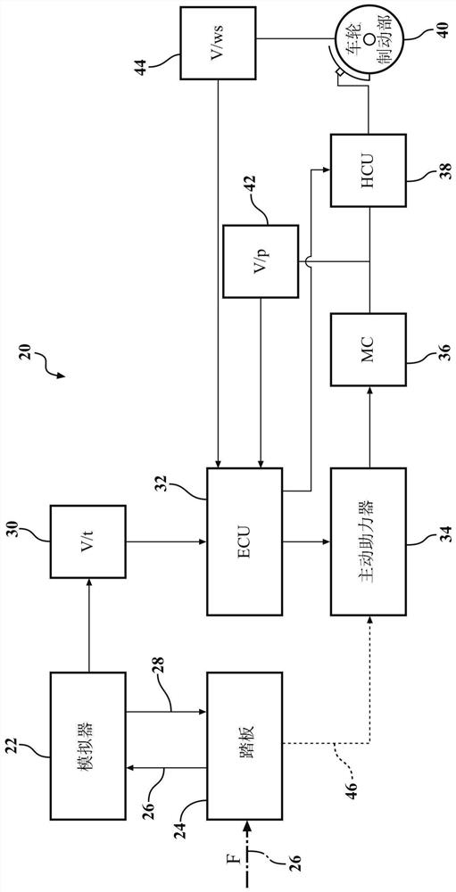
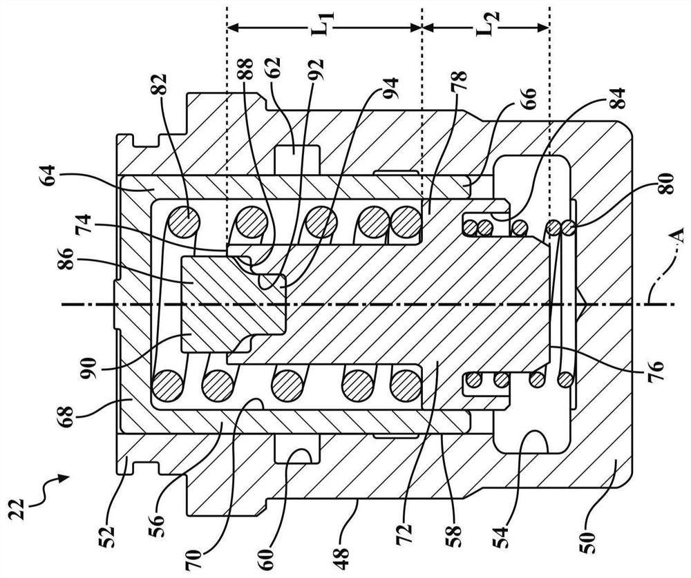
[0014] Referring to the drawings, wherein like reference numerals indicate corresponding parts throughout the several views, in figure 1 A braking system 20 (eg, a brake-by-wire system) including a pedal feel simulator or pedal feel simulator assembly 22 constructed in accordance with an embodiment of the present invention is generally shown in FIG.

[0015] Braking system 20 includes a brake pedal 24 that receives an input force indicated by arrow 26 from a driver of the vehicle. The input force 26 is transmitted through the brake pedal 24 to the pedal feel simulator assembly 22 which also transmits a simulated force / resistance 28 back to the brake pedal 24 . The braking system 20 may include a displacement sensor 30 for monitoring the travel of the brake pedal and transmitting a corresponding signal to the electronic control unit 32 . The electronic control unit 32 may be a central controller of the braking system 20 . Electronic control unit 32 sends control signals to ac...


PUM


Abstract

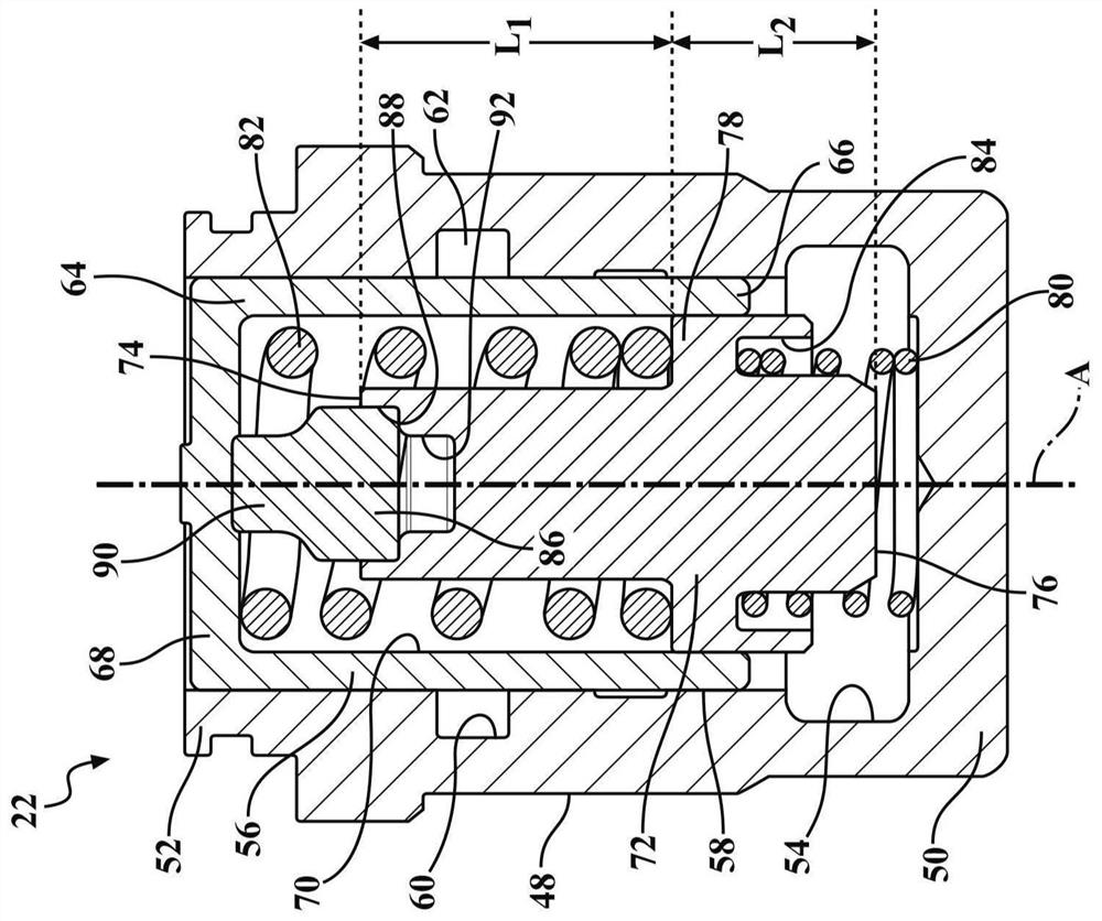
The invention provides a pedal feeling simulator assembly and a brake system. The pedal feel simulator includes a housing extending along a central axis between a closed end and an open end and defining a chamber extending between the closed end and the open end. A first piston is slidably disposed in the chamber. The first piston defines a compartment in fluid communication with the chamber. A second piston is slidably disposed in the compartment. A spring seat extends radially outward from the second piston. A first resilient member is located in the chamber and extends between the spring seat and the closed end. A second resilient member is located in the compartment and extends between the spring seat and the first piston. The third elastic component is located between the second piston and the first piston. The utility model further discloses a brake system comprising the pedal feeling simulator.

Description

technical field [0001] The present invention generally relates to a pedal feel emulator for a braking system. Background technique [0002] Electronic braking systems, such as so-called "brake-by-wire" systems, are increasingly being integrated into or replacing traditional hydraulic braking systems in motor vehicles, including passenger cars, SUVs and light trucks. Such electronic braking systems are preferred because they reduce the weight of the system, provide greater ability to integrate the system into other electronic circuits and controls of the vehicle, and are suitable for use with complex braking control systems. [0003] In a conventional hydraulic braking system, during the time the operator of the vehicle depresses the brake pedal, the hydraulic fluid will exert a reactive force on the brake pedal due to the hydraulic pressure in the brake line. Since the electronic braking system may not have such hydraulic pressure at the brake pedal, the driver of the vehic...

Claims


Application Information

Patent Timeline
IPC IPC(8): B60T8/40
CPCB60T8/409B60T2270/306B60T7/042B60T13/662B60T8/1755B60T8/44B60T13/165B60T13/62B60T2240/00B60T2260/08B60T2270/402B60T2270/404B60T2270/82B60T2270/88
Inventor S·G·霍克西罗东强
Owner BWI (SHANGHAI) CO LTD
Learn More