Double-sided electrodeposition equipment, double-sided electrodeposition method and produced product

An electrodeposition, double-sided technology, applied in the direction of electrodes, electrolytic components, electrolytic process, etc., can solve the problems of nickel foam anti-compression characteristics and poor winding performance, high resistance, small deposition thickness, etc., to improve anti-compression characteristics and Winding performance, improvement of overall nickel plating effect, effect of weakening unevenness

Active Publication Date: 2022-01-04
NAT ENG RES CENT OF ADVANCED ENERGY STORAGE MATERIALS SHEN ZHEN LTD CO
View PDF6 Cites 0 Cited by
  • Summary
  • Abstract
  • Description
  • Claims
  • Application Information

AI Technical Summary

Problems solved by technology

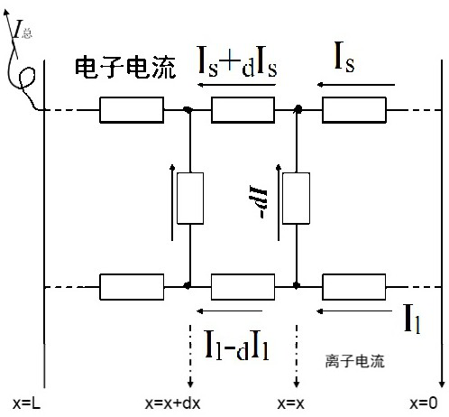
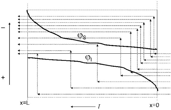
[0002] When manufacturing nickel foam, in the early stage of traditional symmetrical electroplating, the resistance of the foam plastic matrix is ​​relatively high, and the current distribution is mainly concentrated on the collector end. At this time, the amount of nickel plating on the collector side (outside of the foam plastic) is high; (The outer side of the foamed plastic) has a small resistance and is close to the solution phase. If the liquid phase polarization is not considered, the current is mainly concentrated on the outer side. Therefore, the amount of nickel plating on the outer side of the foamed nickel is large, and the middle is less, resulting in foamed nickel. The symmetrical distribution of nickel plating inside and outside, this symmetrical distribution cannot be weakened by secondary electroplating
As a result, the coating thickness of the nickel foam middle layer is small, resulting in a relatively small deposition thickness, and the compression resistance and winding performance of the foam nickel are poor

Method used


Image

  • Double-sided electrodeposition equipment, double-sided electrodeposition method and produced product
  • Double-sided electrodeposition equipment, double-sided electrodeposition method and produced product
  • Double-sided electrodeposition equipment, double-sided electrodeposition method and produced product

Examples


Embodiment Construction

[0036] Embodiments of the present invention are described in detail below, examples of which are shown in the drawings, wherein the same or similar reference numerals designate the same or similar elements or elements having the same or similar functions throughout. The embodiments described below by referring to the figures are exemplary only for explaining the present invention and should not be construed as limiting the present invention.

[0037] In the description of the present invention, it should be understood that the orientation descriptions, such as up, down, front, back, left, right, etc. indicated orientations or positional relationships are based on the orientations or positional relationships shown in the drawings, and are only In order to facilitate the description of the present invention and simplify the description, it does not indicate or imply that the device or element referred to must have a specific orientation, be constructed and operated in a specific ...


PUM

PropertyMeasurementUnit
compressive strengthaaaaaaaaaa

Abstract

The invention discloses a double-sided electrodeposition equipment, a double-sided electrodeposition method and a prepared product. The double-sided electrodeposition equipment includes a front titanium basket and a rear titanium basket. The double-side electrodeposition equipment also includes: electrically connected to the front titanium basket. The first rectifier of the basket is electrically connected to the second rectifier of the rear titanium basket; wherein, the first rectifier is configured to distribute current to the front titanium basket, and the second rectifier is configured to distribute current to the rear titanium basket, and according to a predetermined current distribution Compared with at least two electrodepositions on the product to be electrodeposited, the double-sided electrodeposition equipment according to the embodiment of the present invention controls the current distribution of the front titanium basket and the rear titanium basket by setting the first rectifier and the second rectifier, and according to the predetermined current Distribution ratio Electrodeposition of the product to be electrodeposited at least twice can weaken the unevenness of nickel plating on the inner side of nickel foam and improve the overall nickel plating effect, thereby increasing the deposition thickness and improving the compression resistance of foam nickel and the volume winding performance.

Description

technical field [0001] The invention relates to the field of processing technology, in particular to a double-sided electrodeposition equipment, a double-sided electrodeposition method and a prepared product. Background technique [0002] When manufacturing nickel foam, in the early stage of traditional symmetrical electroplating, the resistance of the foam plastic matrix is ​​relatively high, and the current distribution is mainly concentrated on the collector end. At this time, the amount of nickel plating on the collector side (outside of the foam plastic) is high; (The outer side of the foamed plastic) has a small resistance and is close to the solution phase. If the liquid phase polarization is not considered, the current is mainly concentrated on the outer side. Therefore, the amount of nickel plating on the outer side of the foamed nickel is large, and the middle is less, resulting in foamed nickel. The symmetrical distribution of the amount of nickel plating inside a...

Claims


Application Information

Patent Timeline
Patent Type & Authority Patents(China)
IPC IPC(8): C25D17/00C25D17/10C25D21/12C25D7/00
CPCC25D17/00C25D17/10C25D21/12C25D7/00
Inventor 钟发平肖进春张涛李建奇蒋素斌彭海青
Owner NAT ENG RES CENT OF ADVANCED ENERGY STORAGE MATERIALS SHEN ZHEN LTD CO
Why Eureka
Try Eureka