Carbon ceramic brake disc

A technology of brake discs and carbon ceramics, applied in the field of brake discs, can solve problems such as lack of installation devices, low strength of brake discs, and reduced use efficiency, so as to improve use efficiency and service life, improve heat dissipation effect, and increase service life Effect

Active Publication Date: 2021-09-03
烟台奥森制动材料有限公司
View PDF9 Cites 1 Cited by
  • Summary
  • Abstract
  • Description
  • Claims
  • Application Information

AI Technical Summary

Problems solved by technology

[0004] The purpose of the present invention is to solve the problem that the existing cast iron brake discs are difficult to withstand high temperature, and it is difficult to quickly dissipate the high temperature on it. In addition, the brake disc has low strength and braking In the process, it is very easy to cause the brake disc to be deformed or even cracked. At the same time, the current brake disc does not have an installation device, which is inconvenient to install and greatly reduces the shortcomings of the use efficiency. The proposed carbon ceramic brake disc

Method used


Image

  • Carbon ceramic brake disc
  • Carbon ceramic brake disc
  • Carbon ceramic brake disc

Examples


Embodiment 1

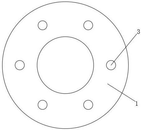
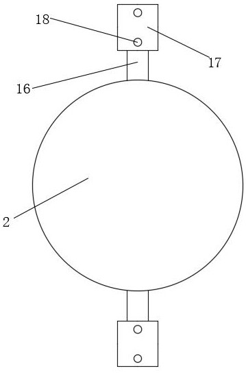
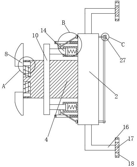
[0029] refer to Figure 1-6 , a carbon ceramic brake disc, including a disc body 1 and a side plate 2. There are several heat dissipation holes 3 on the disc body 1. The disc body 1 is made of carbon ceramics. The left side of the side plate 2 is fixedly installed with a mounting column 4. 4 is slidably installed with a shielding device, the mounting column 4 is slidably installed with a clamping device, two mounting rods 16 are symmetrically fixedly installed on the side plate 2, and mounting plates 17 are fixedly mounted on the two mounting rods 16. Two threaded holes 18 are opened symmetrically on the plate 17, two fixed plates 19 are symmetrically fixedly installed on the side plate 2, fixing devices are slidingly installed on the two fixed plates 19, and two symmetrical threads are installed on the side plate 2. Screw rod 26, two screw rods 26 are correspondingly connected with two fixing devices, two screw rods 26 are fixedly equipped with drive wheels 28, two drive whee...

Embodiment 2

[0040] refer to Figure 1-6 , a carbon ceramic brake disc, including a disc body 1 and a side plate 2, a plurality of cooling holes 3 are opened on the disc body 1, the disc body 1 is made of carbon ceramics, and a mounting column 4 is installed on the left side of the side plate 2 by welding. A shielding device is slidably installed on the column 4, a clamping device is slidably installed on the mounting column 4, two mounting rods 16 are installed symmetrically on the side plate 2 by welding, and a mounting plate 17 is installed on the two mounting rods 16 by welding. Two threaded holes 18 are opened symmetrically on the two mounting plates 17, and two fixing plates 19 are installed symmetrically by welding on the side plate 2, and fixing devices are slidingly installed on the two fixing plates 19, and the symmetrical threads on the side plate 2 Two screw rods 26 are installed, and the two screw rods 26 are connected to the corresponding rotation of the two fixing devices. O...


PUM


Abstract

The invention belongs to the technical field of brake discs, and particularly relates to a carbon ceramic brake disc. By aiming at the problems that an existing cast iron brake disc can hardly bear high temperature, the high temperature on the brake disc is hard to dissipate quickly, in addition, the strength of the brake disc is low, the brake disc is extremely prone to deforming and even cracking in the braking process, meanwhile, the existing brake disc is not provided with a mounting device, mounting is inconvenient, and the use efficiency is greatly reduced, the following scheme is provided, wherein the carbon ceramic brake disc comprises a disc body and a side plate, multiple heat dissipation holes are formed in the disc body, the disc body is made of a carbon ceramic material, a mounting column is fixedly mounted on the left side of the side plate, a shielding device is mounted on the mounting column in a sliding manner, a clamping device is mounted on the mounting column in a sliding manner, and two mounting rods are symmetrically and fixedly mounted on the side plate. The high temperature of the brake disc can be quickly dissipated, the strength of the brake disc is high, the brake disc is not prone to deforming in the braking process, meanwhile, the brake disc is convenient to mount, the use efficiency is greatly improved, and the service life is greatly prolonged.

Description

technical field [0001] The invention relates to the technical field of brake discs, in particular to a carbon ceramic brake disc. Background technique [0002] Carbon ceramic brake disc is a kind of brake disc made of carbon fiber reinforced silicon carbide matrix composite material. During the emergency braking process of the brake disc, the working strength of the brake disc is too large, and the high temperature of thousands of degrees is easy to be generated when the cast iron brake disc brakes. [0003] However, the existing cast iron brake discs are difficult to withstand high temperature, and it is difficult to quickly dissipate the high temperature on it. In addition, the strength of the brake disc is low, and the brake disc is easily deformed or even cracked during the braking process. At the same time, the current brake disc does not Equipped with a mounting device, it is inconvenient to install and greatly reduces the efficiency of use. Contents of the inventio...

Claims


Application Information

Patent Timeline
IPC IPC(8): F16D65/12
CPCF16D65/126F16D65/128
Inventor 张洪波
Owner 烟台奥森制动材料有限公司
Why Eureka
Try Eureka