A vacuum and pressure composite groundwater source heat pump recharge device
A water source heat pump and composite technology, applied in the direction of geothermal energy, geothermal energy power generation, geothermal collectors, etc., can solve the problems of low recharge efficiency, high geological structure requirements, inconvenient recharge, etc., and achieve convenient collection and recharge , the effect of improving efficiency
- Summary
- Abstract
- Description
- Claims
- Application Information
AI Technical Summary
Problems solved by technology
Method used
Image

Examples
Embodiment 1
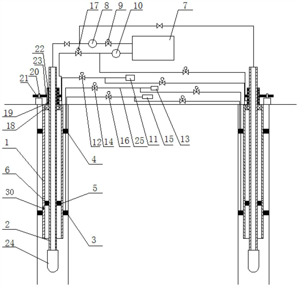
[0032] Such as figure 1 The vacuum and pressure combined ground water source heat pump recharge device shown in the figure includes a hydraulic telescopic outer tube 1 inserted into the hot water well, and the upper end of the hydraulic telescopic outer tube 1 is fixedly connected to the wellhead of the hot water well by pouring sealed cement Together; the inner tube 2 and the heat exchange device 7 that are concentric with the hydraulically expandable outer tube 1 in the hydraulically expandable outer tube 1; the hydraulically expandable outer tube 1 and the inner tube 2 are made of stainless steel anti-corrosion and high temperature resistant materials The heat exchange device 7 is currently the most commonly used heat exchange device in this field, and the specific structure of the heat exchange device is not described in detail in this embodiment; the upper end of the inner tube 2 extends upward, and Extending above the hydraulically telescopic outer tube 1, the lower end ...
Embodiment 2
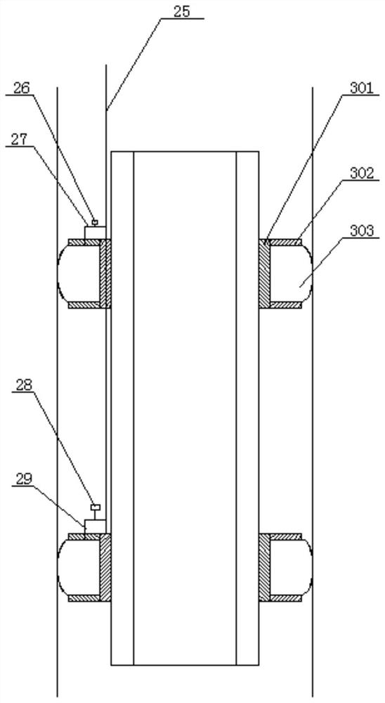
[0046] On the basis of Example 1, the upper air bag packing assembly 4 and the lower air bag packing assembly 3 are the same air bag packing assembly, such as figure 2 The figure shown includes an annular body 301 fixedly sleeved outside the hydraulic telescopic outer tube 1, the upper and lower ends of the annular body 301 are respectively fixed with blocking rings 302, and the space formed by the two blocking rings 302 is fixed with an expansion ring. Air bag 303; the inflation and deflation pipeline 25 extends through the annular body 301 of the upper air bag packing assembly 4 to the ring body 301 in the lower air bag packing assembly 3, and the inflation air bag 303 in the upper air bag packing assembly 4 It communicates with the inflation and deflation pipeline 25 through the upper bronchus 27, and the upper bronchus 27 is provided with a first air valve 26, and the inflation air bag 303 in the lower air bag sealing assembly 3 communicates with the inflation and deflatio...
Embodiment 3
[0048] On the basis of Example 1, such as Figure 4 The hydraulically telescopic outer tube 1 includes an outer cylinder body 101 and an inner water pipe 102 disposed in the outer cylinder body 101, and the inner water pipe 102 is in sealing and sliding connection with the outer cylinder body 101, and the inner wall of the outer cylinder body 101 is provided with Annular cavity 103, this annular cavity 103 forms an oil chamber after being sealed by the outer wall of inner water pipe 102, and described inner water pipe 102 is positioned at the end of annular cavity 103 and is fixedly provided with sealing piston 104, and the outer wall of this sealing piston 104 and The inner wall of the oil chamber is sealed and slidingly connected, and the outer cylinder 101 is respectively provided with an upper oil inlet nozzle 105 and a lower oil inlet nozzle 106 communicating with the oil chamber, and the upper oil inlet nozzle 105 and the lower oil inlet nozzle 106 are respectively locate...
PUM
 Abstract
Description
Claims
Application Information
 - R&D
- Intellectual Property
- Life Sciences
- Materials
- Tech Scout
- Unparalleled Data Quality
- Higher Quality Content
- 60% Fewer Hallucinations
Browse by: Latest US Patents, China's latest patents, Technical Efficacy Thesaurus, Application Domain, Technology Topic, Popular Technical Reports.
© 2025 PatSnap. All rights reserved.Legal|Privacy policy|Modern Slavery Act Transparency Statement|Sitemap|About US| Contact US: help@patsnap.com