Three-inductor high-gain Boost converter

A converter and high-gain technology, applied in the direction of adjusting electrical variables, converting DC power input to DC power output, instruments, etc., can solve problems such as insufficient boosting capacity, difficulty in effectively recovering leakage inductance energy, and low conversion efficiency. Simple structure, reduced current stress, and simple control

Active Publication Date: 2021-09-03
JIANGSU UNIV
View PDF4 Cites 0 Cited by
  • Summary
  • Abstract
  • Description
  • Claims
  • Application Information

AI Technical Summary

Problems solved by technology

Boost converters based on coupled inductors can obtain higher voltage gain by changing the winding ratio of coupled inductors, but the conversion efficiency is usually low due to the difficulty of effectively recovering leakage inductance energy
The boost converter based on switched inductors changes the connection mode of the inductor by controlling the switching off and on of the switching tube, so as to obtain a higher voltage gain; but when used as a renewable energy interface converter, its boosting capability is slightly insufficient

Method used


Image

  • Three-inductor high-gain Boost converter
  • Three-inductor high-gain Boost converter
  • Three-inductor high-gain Boost converter

Examples


Embodiment Construction

[0020] The following will clearly and completely describe the technical solutions in the embodiments of the present application with reference to the accompanying drawings in the embodiments of the present application. Obviously, the described embodiments are only part of the embodiments of the present application, not all of them. Based on the embodiments in this application, all other embodiments obtained by persons of ordinary skill in the art without making creative efforts fall within the protection scope of the present invention.

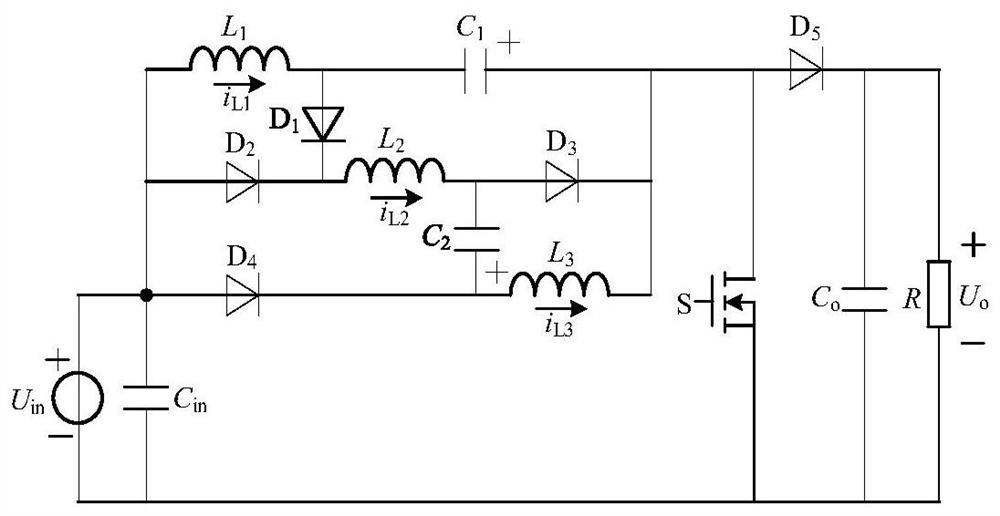
[0021] The invention provides a three-inductance high-gain Boost converter, the circuit structure is as follows figure 1 shown. The high-gain Boost converter includes a DC power supply U in , Input filter capacitor C in , the first inductance L 1 , the second inductance L 2 , the third inductance L 3 , switch tube S, first diode D 1 , the second diode D 2 , the third diode D 3 , the fourth diode D 4 , the fifth diode D 5 , the first ...


PUM


Abstract

The invention discloses a three-inductor high-gain Boost converter. The anode of a direct-current power supply of the converter is connected with an anode of an input filter capacitor, one end of a first inductor, an anode of a second diode and an anode of a fourth diode; the other end of the first inductor is connected with the anode of a first diode and the cathode of a first capacitor; the cathode of the first diode is connected with one end of a second inductor and the cathode of the second diode; the other end of the second inductor is connected with the anode of a third diode and the cathode of a second capacitor ; the anode of the second capacitor is connected with the cathode of a fourth diode and one end of an third inductor; the other end of the third inductor is connected with the anode of the first capacitor, the cathode of the third diode, the anode of a fifth diode and the drain of a switching tube; the cathode of the fifth diode is connected with the anode of an output filter capacitor and one end of a direct-current load; and the other end of the direct-current load is connected with thecathode of the output filter capacitor, the source of the switching tube, the cathode of an input filter capacitor and the cathode of an input power supply.

Description

technical field [0001] The invention belongs to the technical field of DC-DC step-up converters, and in particular relates to a three-inductance high-gain Boost converter. Background technique [0002] In recent years, the problems of environmental pollution and energy shortage have aroused great concern all over the world. For this reason, non-polluting and renewable energy sources such as solar energy and wind energy have been rapidly developed. However, the terminal voltages of renewable energy generating units such as fuel cells and photovoltaic cells are low and vary widely. Therefore, the distributed renewable energy grid-connected power generation system generally adopts a two-stage structure of a DC boost converter cascaded with a voltage-type inverter. At present, the leakage current suppression strategy of non-isolated grid-connected inverters is becoming more and more mature, and the electrical safety problem has been perfectly solved. Moreover, compared with i...

Claims


Application Information

Patent Timeline
Patent Type & Authority Applications(China)
IPC IPC(8): H02M3/156
CPCH02M3/156
Inventor 秦杨许兴
Owner JIANGSU UNIV
Why Eureka
Try Eureka