Adjustment drive having a brush card assembly with integrated printed circuit board

A technology for regulating drives, printed circuit boards, applied to electromechanical devices, electric components, and connections to control/drive circuits, etc.

Pending Publication Date: 2021-09-03
NIDEC MOTORS & ACTUATORS GERMANY GMBH
View PDF0 Cites 0 Cited by
  • Summary
  • Abstract
  • Description
  • Claims
  • Application Information

AI Technical Summary

Problems solved by technology

This results in the need for a ne...

Method used


Image

  • Adjustment drive having a brush card assembly with integrated printed circuit board
  • Adjustment drive having a brush card assembly with integrated printed circuit board
  • Adjustment drive having a brush card assembly with integrated printed circuit board

Examples


Embodiment Construction

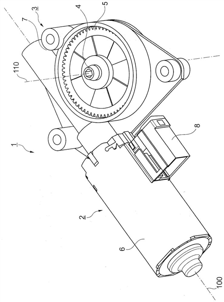
[0024] figure 1 The adjusting drive 1 comprising a brushed DC motor 2 and a gear 3 is shown in . In commutator motors, the current from the power supply or control unit is supplied via brushes, which are applied to the commutator, which is divided into laminations and serves to divert the current. The laminations are insulated from each other on the circumference of the commutator and, as the rotor formed by the armature winding, motor shaft and commutator turns, current is supplied in turn via the brushes accordingly. A direct voltage, such as a PWM signal, is applied to the brushes by a control device not shown, so that the current is established. The DC motor 2 is designed to drive an output shaft 4 . The transmission device 3 arranged between the DC motor 2 and the output shaft 4 is preferably a worm gear transmission device. The motor shaft is preferably designed as a worm. The corresponding worm gear 5 is mounted on the output shaft 4 . For the geometric description...


PUM


Abstract

The invention relates to an adjustment drive (1) having a brushed DC motor (2), a brush card assembly (8) having electrical contacts for the brushes to busbars (10), a Hall sensor arrangement (15, 16) and a gear unit (3), wherein: the Hall sensor arrangement (15, 16) is arranged on a printed circuit board (14) which is integrated in the brush card assembly (8); a pin connection (17) is arranged on the printed circuit board (14) for contacting the Hall sensor arrangement (15, 16); and the brush card assembly (8) has a plug body (11) with a plug collar (19), the plug body (11) being at least partially penetrated by the pin connection (17) and the busbars (10) to form a plug.

Description

technical field [0001] The invention relates to an adjusting drive having the features of the preamble to variant 1 . Background technique [0002] Multi-pole brushed DC motors for motor vehicles use bus bars to conduct current between the motor's electrical connectors and associated components such as chokes, capacitors and brushes. Traditional busbars must be fabricated and physically attached, supported and connected to the motor. Typically, the busbars are riveted to the brush plates of the motor. Electrical connections are usually made using soldered or thermally bonded joints. In addition, a position sensor is provided to detect the angular position of the rotor of the DC motor. The position sensor is preferably a Hall sensor. Traditionally, Hall sensors are plugged into wired brush boards. This results in the need for new wire cuts for each new connector design. In addition, a motor disturbance suppression device and a Hall circuit need to be arranged separately...

Claims


Application Information

Patent Timeline
IPC IPC(8): H02K7/116H02K11/215H02K5/22H02K11/38H02K5/14
CPCH02K7/1166H02K11/215H02K5/225H02K11/38H02K5/148H02K2203/09H02K2211/03H02K2213/12H02K29/08
Inventor N·赫尔曼M·史温
Owner NIDEC MOTORS & ACTUATORS GERMANY GMBH
Why Eureka
Try Eureka