Door frame flange production device provided with multi-stage heating section and used for wind power tower
A technology for wind power towers and production equipment, applied in metal processing equipment, heating/cooling equipment, mechanical equipment, etc., can solve the problems of low production efficiency, high production cost, discontinuous fibers, etc., to improve production quality and improve use. Longevity and effect of improving molding quality
- Summary
- Abstract
- Description
- Claims
- Application Information
AI Technical Summary
Problems solved by technology
Method used
Image

Examples
Embodiment 1
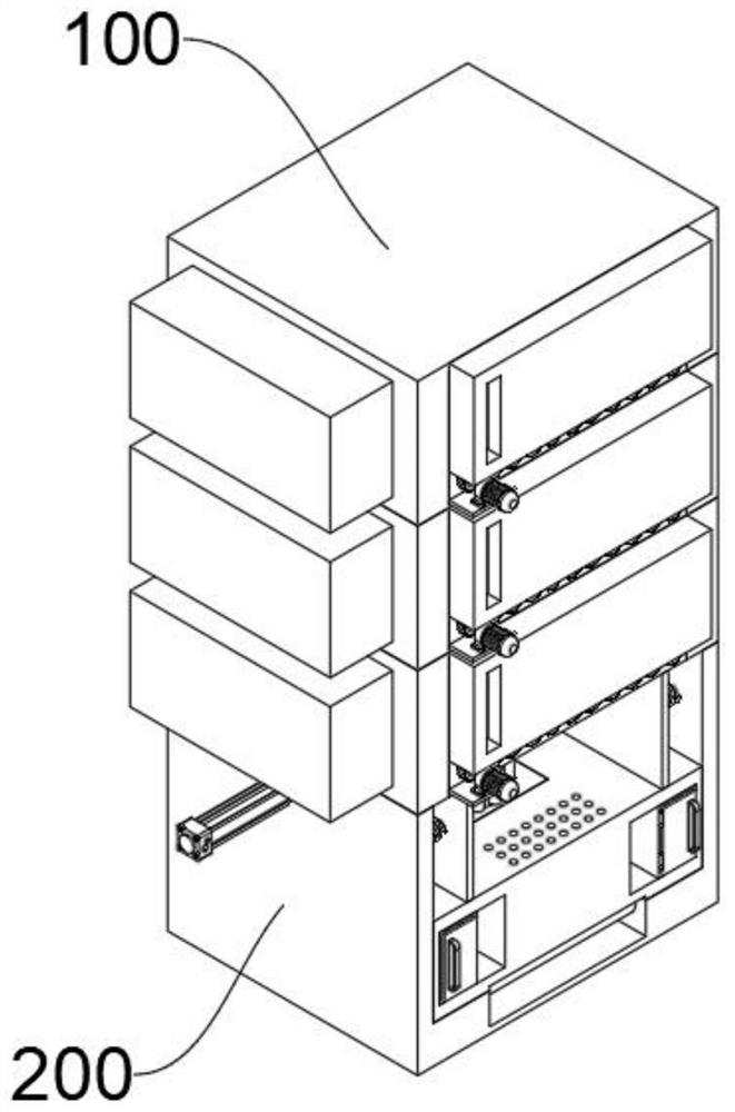
[0042] see Figure 1-Figure 6As shown, this embodiment provides a door frame flange production equipment for wind power towers equipped with multi-stage heating sections, at least including:
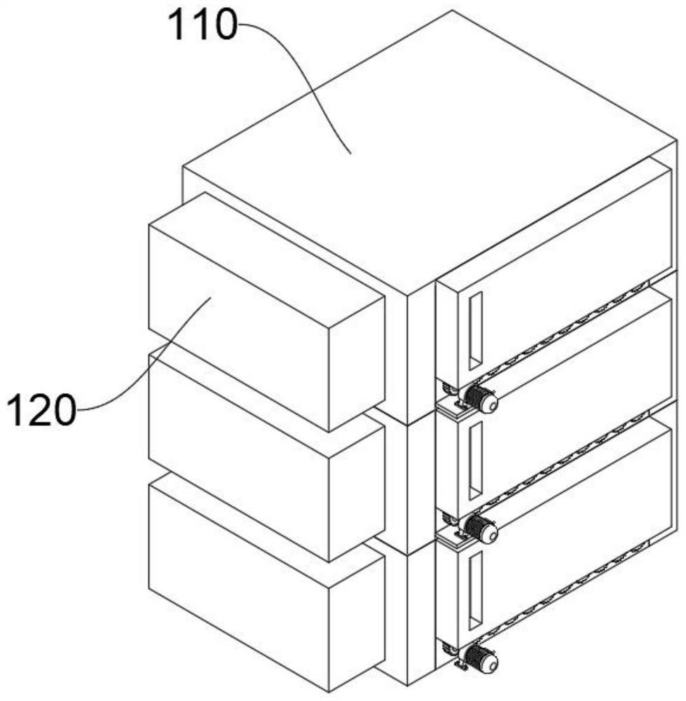
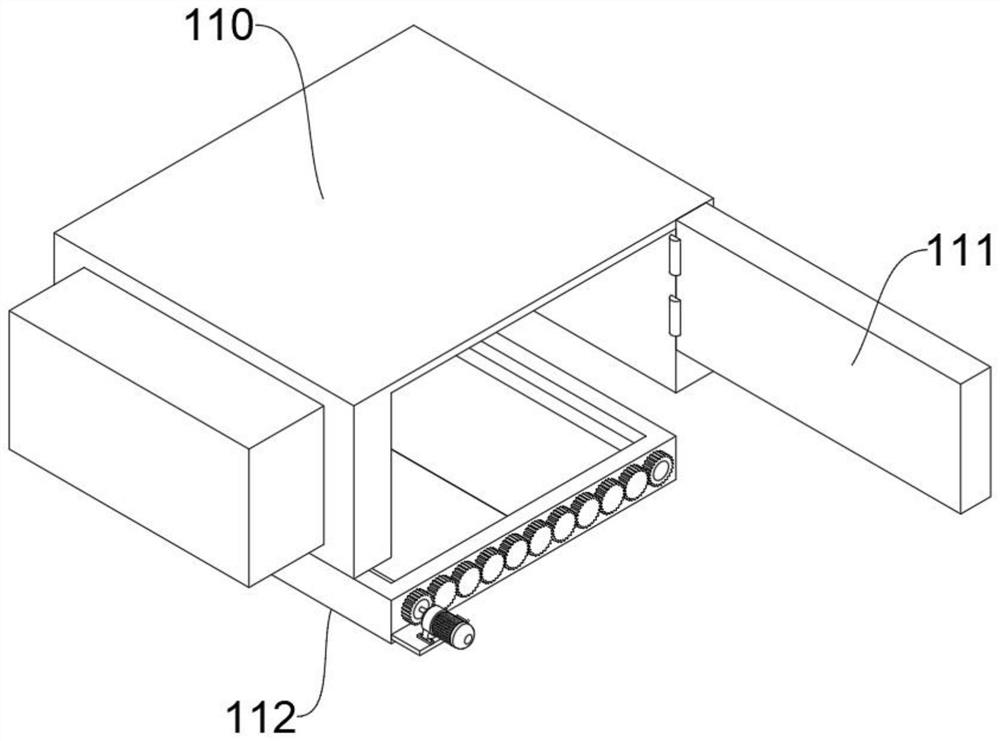
[0043] The multi-stage heating mechanism 100, the multi-stage heating mechanism 100 includes three heating boxes 110, the opening of the outer wall of the heating box 110 is hinged with a sealed door 111, through the sealed door 111 it is convenient to take and place the blank, the three heating boxes 110 are connected internally, and the heating box The outer wall of 110 is connected with a coal-fired heater 120, and when the billet is placed inside the heating box 110, the coal in the coal-fired heater 120 is burned to generate heat, so that the heat is diffused inside the heating box 110 to ensure structural integrity. 110 is provided with a fixed frame 112 in the inner cavity near the bottom, and two symmetrical control gates 113 are arranged for rotation inside the fixed frame 112. ...
Embodiment 2
[0050] In order to avoid hitting the inner wall of the forging box 200, which is beneficial to improve the service life of the forging box 200, the difference between this embodiment and the embodiment 1 is that please refer to 7, wherein:
[0051] A buffer spring 222 is fixedly connected between the beating plate 221 and the inner wall of the forging box 200. Through the buffer spring 222, when the beating plate 221 moves with the output rod of the hydraulic machine 220, it can be performed when the beating plate 221 is close to the inner wall of the forging box 200. Buffering, to avoid hitting the inner wall of the forging box 200, which is beneficial to improve the service life of the forging box 200, the buffer spring 222 is provided with a fixed rod 2221, the end of the fixed rod 2221 is fixedly connected to the inner wall of the forging box 200, and the inside of the fixed rod 2221 is slidingly provided with The piston rod 2222, the end of the piston rod 2222 slides out o...
Embodiment 3
[0053] For the convenience of taking out the forged piece after forging, the difference between this embodiment and Embodiment 1 is that please refer to Figure 8-Figure 9 shown, where:
[0054] There is a groove 230 at the bottom of the inner cavity of the forging box 200, and a plurality of transmission rollers 231 are arranged in rotation inside the groove 230. The outer wall of the transmission roller 231 is closely attached to the bottom of the support plate 210, so that after the forging is completed, the plurality of transmission rollers 231 When rotating at the same time, the conveying roller 231 rolls along the bottom of the support plate 210, driving the support plate 210 to slide out of the forging box 200, which is convenient for taking out the forging after the forging is finished, and is more practical.
[0055] Specifically, the ends of the transmission rollers 231 rotate and extend into the inner layer of the forging box 200 to be fixedly connected with a drive...
PUM
 Abstract
Description
Claims
Application Information
 - R&D
- Intellectual Property
- Life Sciences
- Materials
- Tech Scout
- Unparalleled Data Quality
- Higher Quality Content
- 60% Fewer Hallucinations
Browse by: Latest US Patents, China's latest patents, Technical Efficacy Thesaurus, Application Domain, Technology Topic, Popular Technical Reports.
© 2025 PatSnap. All rights reserved.Legal|Privacy policy|Modern Slavery Act Transparency Statement|Sitemap|About US| Contact US: help@patsnap.com