Workpiece loading mechanism and workpiece assembling equipment

A technology for assembling equipment and workpieces, applied in metal processing equipment, metal processing, manufacturing tools, etc., can solve problems such as high cost, low efficiency, and high scrap rate

Active Publication Date: 2021-09-07
JIANGSU CHUANGYUAN ELECTRON CO LTD
View PDF5 Cites 4 Cited by
  • Summary
  • Abstract
  • Description
  • Claims
  • Application Information

AI Technical Summary

Problems solved by technology

[0002] In the prior art, in the assembly process of MOS tubes and radiators, most of the MOS tubes are loaded and assembled manually, which consumes a lot of manpower, not o

Method used


Image

  • Workpiece loading mechanism and workpiece assembling equipment
  • Workpiece loading mechanism and workpiece assembling equipment
  • Workpiece loading mechanism and workpiece assembling equipment

Examples


Embodiment 1

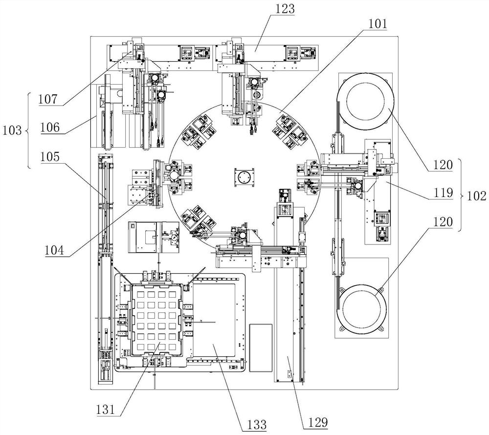
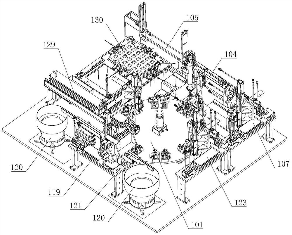
[0056] see Figure 1 to Figure 8 As shown, the workpiece assembly equipment provided by the present application includes a transfer mechanism 101 and a first feeding mechanism 102, a second feeding mechanism 103 (corresponding to the workpiece feeding mechanism) and an assembly mechanism arranged in sequence on the running path of the transfer mechanism 101 104. Such as figure 1 and figure 2 As shown, the transfer mechanism 101 shown in the figure is a circular turntable that rotates counterclockwise, and a plurality of installation positions are formed on the peripheral edge of the circular turntable to install workpieces. The first feeding mechanism 102, the second feeding mechanism 103 and the assembly mechanism 104 are arranged in the circumferential direction of the turntable. Such setting makes the devices more compact and the equipment takes up less space.

[0057] Optionally, the transfer mechanism 101 may also be a transport structure such as a conveyor belt with...

Embodiment 2

[0074] The workpiece assembly equipment in the second embodiment is an improvement on the basis of the above embodiment, and the technical content disclosed in the above embodiment will not be described repeatedly, and the content disclosed in the above embodiment also belongs to the content disclosed in the second embodiment.

[0075] see figure 1 and figure 2 As shown, in an optional solution of this embodiment, the first feeding mechanism 102 includes a first feeding assembly 119 and at least one vibrating plate 120 . Wherein, two vibrating plates 120 are shown in the figure, which can respectively feed radiators of two sizes, large and small.

[0076]The vibration plate 120 includes a fixed seat and a plate body installed on the fixed seat, a quantity detection member and a discharge track 121, so as to transport a preset number of first workpieces to the discharge track 121; the discharge track 121 of a plurality of vibration plates 120 The tail end of is set at the fi...


PUM


Abstract

The invention relates to the field of machining equipment, in particular to a workpiece loading mechanism and workpiece assembling equipment. The workpiece loading mechanism comprises a feeding assembly, a pretreatment assembly and a second loading assembly. To-be-loaded workpieces are field-effect tubes; the feeding assembly is used for separating the multiple field-effect tubes loaded in containing tubes one by one, the second loading assembly is used for conveying the separated field-effect tubes to the pretreatment assembly, and the pretreatment assembly is used for pretreating pins of the field-effect tubes; the second loading assembly is further used for conveying the pretreated field-effect tubes to next process equipment; and the second loading assembly comprises a loading adsorption part and a driving assembly for driving the loading adsorption part to move in the three perpendicular directions, and the loading adsorption part is used for adsorbing or releasing the field-effect tubes. According to the workpiece loading mechanism, the to-be-loaded workpieces can be automatically loaded, the efficiency is higher, the subsequent assembling position is more accurate, and the stability of assembled products can be improved.

Description

technical field [0001] The present application relates to the field of processing equipment, in particular to a workpiece feeding mechanism and workpiece assembly equipment. Background technique [0002] In the prior art, in the assembly process of MOS tubes and radiators, most of the MOS tubes are loaded and assembled manually, which consumes a lot of manpower, not only low efficiency and high cost, but also manual operation will cause inaccurate assembly positions , thus affecting the stability of the product, and the scrap rate is high. Contents of the invention [0003] The purpose of this application is to provide a workpiece loading mechanism and workpiece assembly equipment, which can be used for automatic loading of MOS tubes, with higher efficiency and more accurate subsequent assembly positions. [0004] The application provides a workpiece feeding mechanism, including a feeding assembly, a preprocessing assembly and a second feeding assembly; [0005] The work...

Claims


Application Information

Patent Timeline
IPC IPC(8): B23P19/00B23Q7/02B65G47/14B65G47/91B65G47/82B05C5/00
CPCB23P19/001B23Q7/02B65G47/1421B65G47/912B65G47/82B05C5/002
Inventor 王静松
Owner JIANGSU CHUANGYUAN ELECTRON CO LTD
Why Eureka
Try Eureka