
Intelligent multi-rotor rescue thrower and control method

A thrower and rotor technology, applied in the field of rescue equipment automation and flight control, can solve the problems that the throwing effect depends on the technical level of the thrower, the projectile cannot be modified and changed, and the throwing effect is easily affected by external factors.

Pending Publication Date: 2021-09-07
JIANGSU UNIV
View PDF0 Cites 2 Cited by
  • Summary
  • Abstract
  • Description
  • Claims
  • Application Information

AI Technical Summary

Problems solved by technology

However, this type of thrower mainly uses artificial projection, and whether the projection effect is ideal depends largely on the projection level of the shooter.
Moreover, the projection effect will also be affected by external factors such as weather
[0005] The traditional rescue thrower has the following disadvantages: (1) The throwing effect is too dependent on the skill level of the caster, and it is difficult for non-professionals to use it directly; (2) The throwing effect is easily affected by external factors, such as temperature and humidity during projection , wind speed, etc.; (3) After the throwing projectile pops up, the trajectory and landing point of the projectile cannot be corrected and changed, so it is impossible to respond to the ever-changing dangerous situation in time

Method used


Image

  • Intelligent multi-rotor rescue thrower and control method
  • Intelligent multi-rotor rescue thrower and control method
  • Intelligent multi-rotor rescue thrower and control method

Examples


Embodiment Construction

[0027] Below in conjunction with accompanying drawing and example the present invention will be further described.

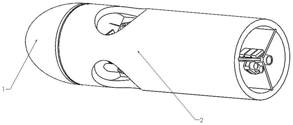
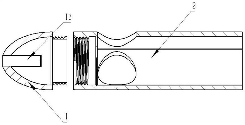
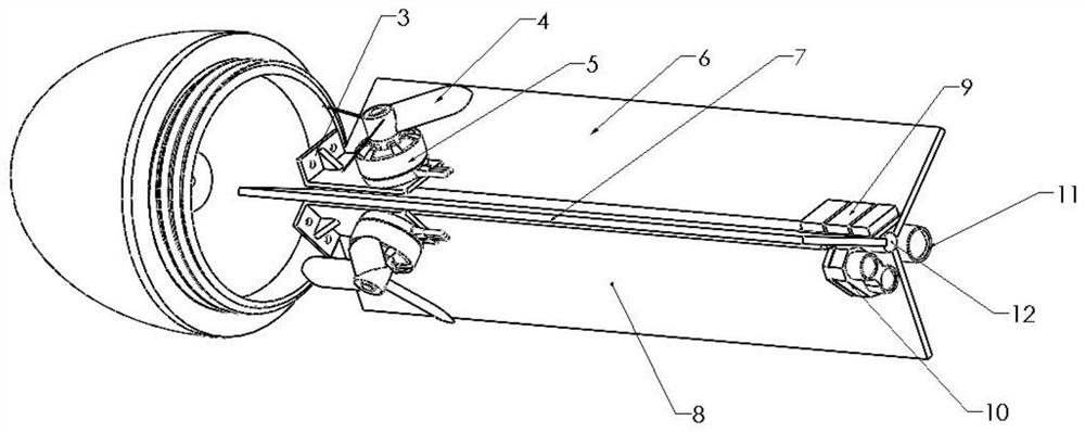
[0028] A thrower structure with a rotor, comprising a projectile warhead 1, a projectile shell 2, a connecting flange 3, a rotor 4, a motor 5, a first diverter plate 6, a second diverter plate 7, a third diverter plate 8, a flying Control module 9, vision module 10, laser radar 11, battery 12, umbrella storage bin 13. This throwing device contains three rotors 4 altogether, and all are built in in the throwing bin, and three rotors are mutually 120 degrees, constitute equilateral triangle and face outside installation. None of the three rotors are used to provide lift during ascent. They only need to provide lateral force to change the pose of the thrower when the thrower reaches the highest point and then fall, so as to achieve accurate positioning of the landing point, so the rotor does not need Too much power is generated, that is, the corresponding motor po...


PUM


Abstract

The invention discloses an intelligent multi-rotor rescue thrower and a control method, a throwing warhead is located at the foremost end of the thrower and plays a role in breaking wind and reducing resistance in the rising process of the thrower, a parachute storage bin is installed in the center of the front end of the throwing warhead, the rear end of the throwing warhead is connected with a projectile body shell through threads, a first splitter plate, a second splitter plate and a third splitter plate are directly connected with the projectile body shell through a built-in chute of the projectile body shell to equally divide the space in the cavity of the projectile body shell; the projectile body shell is tightly connected with the motor through a connecting flange, the upper end of the motor is connected with rotor wings, and the three rotor wings 4 are arranged in the cavity of the projectile body shell and are separated by a splitter plate to provide power for the system; the thrower structure is further provided with a flight control module, and a visual module, a laser radar and a battery which are connected with the flight control module. According to the invention, the hang time of the thrower is greatly increased, and when the thrower falls, the drop point position is intelligently identified and the rotor wings are controlled to make yawing motion, so that the purpose of tracking the drop point is achieved and the energy loss is reduced at the same time.

Description

technical field [0001] The invention relates to the technical field of rescue equipment automation and flight control, in particular to an intelligent thrower for the purpose of multi-rotor controllable fixed-point tracking. Background technique [0002] Force majeure geological disasters pose a great threat to the safety of people's lives and properties. In special situations such as flood relief and sea rescue, people are often trapped and need emergency rescue, but at the same time the trapped people are not easy to be directly contacted. In this case, the rescue environment is generally very bad, and the chance of rescue is fleeting, so the requirements for rescue conditions are relatively high. Under normal conditions, when a major disaster occurs, military and police forces are used to rescue. Because of professional life-saving skills and rescue equipment, they can often successfully help the trapped people out of trouble. But in some emergencies, because it takes ti...

Claims


Application Information

Patent Timeline
IPC IPC(8): B63C9/26
CPCB63C9/26F42B12/36F42B10/56F42B10/58F42B12/56
Inventor 沈跃李奕岑王德伟王秀丽施志翔
Owner JIANGSU UNIV
Learn More