Thickened oil viscosity reducer as well as preparation method and application thereof

A technology of viscosity reducer and heavy oil, which is applied in chemical instruments and methods, earthwork drilling and production, wellbore/well components, etc. It can solve the problems of low viscosity reduction efficiency of heavy oil and achieve the effect of increasing viscosity reduction rate

Active Publication Date: 2021-09-07
YANGTZE UNIVERSITY
View PDF9 Cites 0 Cited by
  • Summary
  • Abstract
  • Description
  • Claims
  • Application Information

AI Technical Summary

Problems solved by technology

[0006] The purpose of the present invention is to overcome the above-mentioned technical deficiencies, provide a heavy oil viscosity reducer and its preparation method and application, and solve the technical problem of low viscosity reduction efficiency of heavy oil in the prior art

Method used


Image

  • Thickened oil viscosity reducer as well as preparation method and application thereof
  • Thickened oil viscosity reducer as well as preparation method and application thereof
  • Thickened oil viscosity reducer as well as preparation method and application thereof

Examples


Embodiment 1

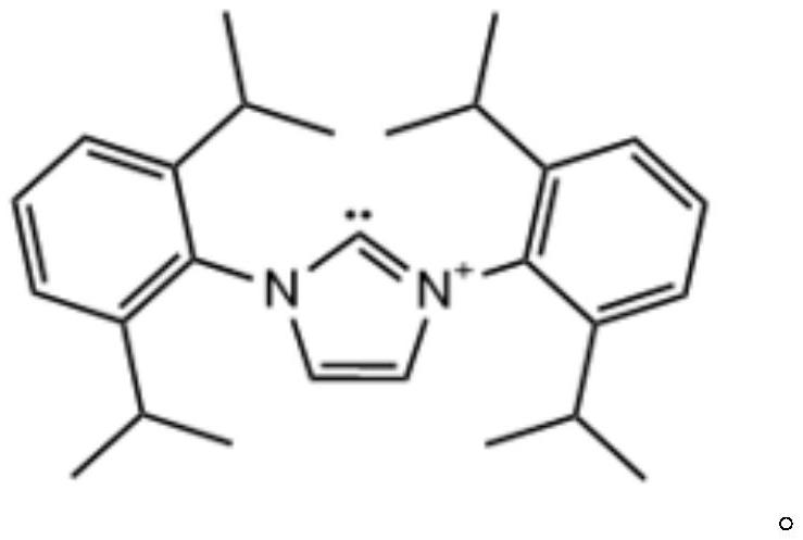
[0035] This example proposes a thick oil viscosity reducer, calculated according to mass percentage, including: free azacarbene 5wt%, tert-butyl hydroperoxide 30wt%, hydrogen donor methanol 5wt%, phosphoric acid 5wt%, emulsifier Span 60 0.5wt%, the rest is solvent benzene, 100% in total.

[0036] The preparation method of the heavy oil viscosity reducer in this example includes the following steps: according to the proportion, mix the free azacarbene with the solvent benzene at 20°C, then add the emulsifier Span 60 and the hydrogen donor methanol to continue mixing , then add tert-butyl hydroperoxide and phosphoric acid to continue mixing to obtain the thick oil viscosity reducer.

Embodiment 2

[0038] This example proposes a heavy oil viscosity reducer, calculated according to mass percentage, including: free azacarbene 7wt%, tert-butyl hydroperoxide 25wt%, hydrogen donor ethanol 2wt%, phosphoric acid 6wt%, emulsifier Span 80 0.7wt%, the rest is solvent benzene, 100% in total.

[0039] The preparation method of the heavy oil viscosity reducer in this example includes the following steps: according to the proportion, mix the free azacarbene with the solvent benzene at 30°C, then add the emulsifier Span 80 and the hydrogen donor ethanol to continue mixing , then add tert-butyl hydroperoxide and phosphoric acid to continue mixing to obtain the thick oil viscosity reducer.

Embodiment 3

[0041] This example proposes a thick oil viscosity reducer, calculated according to mass percentage, including: free azacarbene 8wt%, tert-butyl hydroperoxide 20wt%, hydrogen donor formic acid 3wt%, phosphoric acid 10wt%, emulsifier Span 60 1wt%, and the rest is solvent cyclohexane, totaling 100%.

[0042] The preparation method of the heavy oil viscosity reducer in this example includes the following steps: according to the proportion, mix the free azacarbene with the solvent cyclohexane at 30°C, and then add the emulsifier Span 60 and the hydrogen donor formic acid Continue mixing, then add tert-butyl hydroperoxide and phosphoric acid and continue mixing to obtain the thick oil viscosity reducer.


PUM


Abstract

The invention discloses a thick oil viscosity reducer as well as a preparation method and an application thereof, and belongs to the technical field of thick oil viscosity reduction. The heavy oil viscosity reducer comprises the following components in percentage by mass: 5-10% of free N-heterocyclic carbene, 15-30% of tert-butyl hydroperoxide, 1-5% of a hydrogen donor, 5-10% of phosphoric acid, 0.5-1% of an emulsifier and the balance of a solvent, totaling 100%. The preparation method comprises the following steps: mixing the free N-heterocyclic carbene and the solvent according to the ratio, then adding the emulsifier and the hydrogen donor for continuous mixing, and then adding the tert-butyl hydroperoxide and the phosphoric acid for continuous mixing to obtain the heavy oil viscosity reducer. The invention also discloses an application of the thickened oil viscosity reducer or the thickened oil viscosity reducer prepared by the preparation method in degradation of thick oil. According to the heavy oil viscosity reducer provided by the invention, the viscosity reduction rate can be increased to 90% or above.

Description

technical field [0001] The invention relates to the technical field of heavy oil viscosity reduction, in particular to a heavy oil viscosity reduction agent and its preparation method and application. Background technique [0002] Heavy oil recovery technologies mainly include steam huff and puff, steam flooding, steam assisted gravity drainage (SAGD), electric heating, burning oil layers, catalytic hydrothermal cracking, sand production cold recovery, supercritical extraction, etc. At present, the commonly used production methods include air injection low-temperature catalytic oxidation oil recovery technology for heavy oil, but its safety has always been the focus of academic attention, especially the safety of production wells. It must be ensured that when the air breaks through, the O in the produced gas 2 The concentration is lower than the explosion safety threshold (5%). The safety of this oxidation source is directly related to the promotion and application of this ...

Claims


Application Information

Patent Timeline
IPC IPC(8): C09K8/58E21B43/22
CPCC09K8/58E21B43/16Y02P20/54
Inventor 马兆菲吴配月颜学敏李颢杨欢程仲富邓飞
Owner YANGTZE UNIVERSITY
Why Eureka
Try Eureka