
Deviation rectifying method for soil layer pile foundation

A pile foundation and soil layer technology, applied in the field of soil layer pile foundation deviation correction, can solve the problems of rising cost, time-consuming and laborious process of repositioning, and delay, and achieve the effect of increasing cost, reducing damage and small contact area.

Pending Publication Date: 2021-09-07
GUIZHOU ELECTRIC POWER DESIGN INST
View PDF5 Cites 0 Cited by
  • Summary
  • Abstract
  • Description
  • Claims
  • Application Information

AI Technical Summary

Problems solved by technology

[0004] However, the problem of re-taking out the drill bit and drill pipe is that the process of taking out and repositioning is time-consuming and laborious, and the inclined part cannot be used, which slows down the progress of the project and leads to an increase in cost
The existence of the above-mentioned technical problems is due to the fact that a small inclination after the drill pipe length is too large will cause a huge inclination of the pile hole, which is currently insurmountable
[0005] Due to the defects of the existing pile hole drilling technology, it is impossible to ensure that the pile holes are not inclined without increasing the cost and slowing down the progress of the project.
[0006] The existence of this technical problem hinders the further development of the existing technology
At the same time, since this problem is caused by the defects of the technical ideas of the existing technology, the existing technology cannot solve this technical problem with technical contradictions. Therefore, it is required to , ensuring that the pile hole is not inclined is a technical problem that the technical field has been eager to solve but has not been successful

Method used


Image

  • Deviation rectifying method for soil layer pile foundation
  • Deviation rectifying method for soil layer pile foundation
  • Deviation rectifying method for soil layer pile foundation

Examples


Embodiment 1

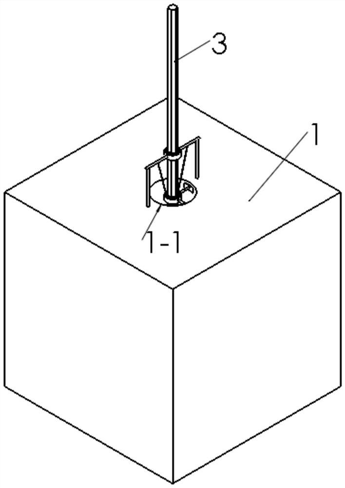
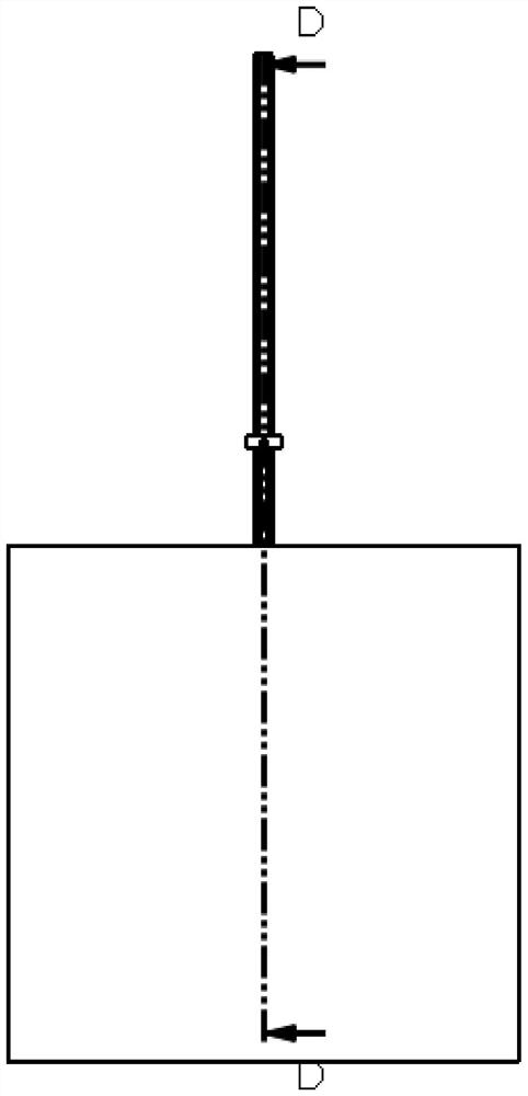
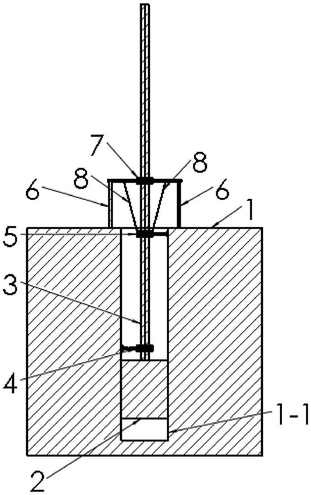
[0054] Implementation Example 1: Reference Figure 1 to Figure 7 , in order to ensure that the pile hole 1-1 is not inclined without increasing the cost and slowing down the progress of the project, the invention provides a method for rectifying the deviation of the pile foundation in the soil layer, and the method includes the following steps:

[0055] S01, drilling initial pile holes on soil layer 1;

[0056] S02, rotate and connect the first telescopic mechanism 4 and the second telescopic mechanism 5 at the drill pipe 3, the first telescopic mechanism 4 is perpendicular to the drill pipe 3, the second telescopic mechanism 5 is perpendicular to the drill pipe 3, and the second telescopic mechanism 5 is perpendicular to the first telescopic mechanism 5. The expansion and contraction directions of the telescopic mechanism 4 are opposite and parallel, and both the first telescopic mechanism 4 and the second telescopic mechanism 5 are located in the initial pile hole;

[0057]...


PUM


Abstract

The invention discloses a deviation rectifying method for a soil layer pile foundation. The method comprises the following steps that S01, an initial pile hole is drilled in a soil layer; S02, a first extendable mechanism and a second extendable mechanism are rotationally connected to a drill rod, the first extendable mechanism is perpendicular to the drill rod, the second extendable mechanism is perpendicular to the drill rod, and the extendable directions of the second extendable mechanism and the first extendable mechanism are opposite and parallel; and S03, the levelness of the first extendable direction mechanism and the second extendable direction mechanism is measured, if the end, away from the drill rod, of the second extendable mechanism is inclined downwards, the second extendable mechanism is controlled to extend, and the first extendable mechanism is controlled to extend till the first extendable mechanism or the second extendable mechanism is horizontal; and if the end, away from the drill rod, of the second extendable mechanism is inclined upwards, the first extendable mechanism is controlled to extend, and the second extendable mechanism is controlled to retract till the first extendable mechanism or the second extendable mechanism is horizontal. The problem that in the prior art, it cannot be guaranteed that a pile hole is not inclined under the conditions that cost is not increased and the project progress is not slowed down is solved.

Description

technical field [0001] The invention relates to a method for rectifying the deviation of pile foundations in soil layers, and belongs to the technical field of pile foundations in soil layers. Background technique [0002] Soil layer pile foundation needs to drill pile holes on the soil layer. Existing pile hole mainly uses drill rod to drive drill bit on soil layer by drilling rig. [0003] There is often the problem of pile hole inclination through the drilling rig, especially when the depth of the pile hole is deep. , just immediately take out the drill bit and the drill pipe and reposition it, and continue drilling on the basis of the original pile hole after correcting the direction of the drill bit and drill pipe, so as to ensure the vertical of the pile hole. [0004] However, the problem of re-taking out the drill bit and drill pipe is that the process of taking out and repositioning is time-consuming and laborious, and the inclined part cannot be used, which slows...

Claims


Application Information

Patent Timeline
IPC IPC(8): E02D35/00
CPCE02D35/00
Inventor 汪俊虎白淑娟邓健刘小林龙欢张少川
Owner GUIZHOU ELECTRIC POWER DESIGN INST
Learn More