Guide limiting block for pipe shoe and installation method of guide limiting block

A technology of limit blocks and pipe shoes, which is applied in the direction of pipe support, pipe protection, pipe laying and maintenance, etc., can solve problems such as cumbersome construction procedures, leftover painting quality problems, and inconvenient installation of pipe shoes

Pending Publication Date: 2021-09-07
OFFSHORE OIL ENG
View PDF6 Cites 0 Cited by
  • Summary
  • Abstract
  • Description
  • Claims
  • Application Information

AI Technical Summary

Problems solved by technology

[0002] In the petrochemical industry, there are often a large number of densely arranged pipeline systems, including offshore oil production platforms. The pipeline system is complex and the layout space is limited. Insufficient dead angle that cannot be painted, there is difficulty in anti-corrosion coating of the guide limit block of the pipeline pipe shoe, and the remaining coating quality problems bring great quality and safety risks to the subsequent pipeline operation and commissioning
[0003] In the traditional design, the guide limit block is usually designed as an angle steel or T-shaped steel guide limit form. The bottom plate and the pipeline support platform are clamped by the angle steel or T-shaped steel. Usually, the limit block needs to be installed first and then the The pipe shoe of the pipeline is stuck in the gap of the limit block, and finally the pipeline and the pipe shoe are installed and fixed. The gap is small, the pipe shoe is inconvenient to ins...

Method used


Image

  • Guide limiting block for pipe shoe and installation method of guide limiting block
  • Guide limiting block for pipe shoe and installation method of guide limiting block
  • Guide limiting block for pipe shoe and installation method of guide limiting block

Examples


Embodiment Construction

[0034] The present invention will be further described below in conjunction with the accompanying drawings and specific embodiments, so that those skilled in the art can better understand the present invention and implement it, but the examples given are not intended to limit the present invention.

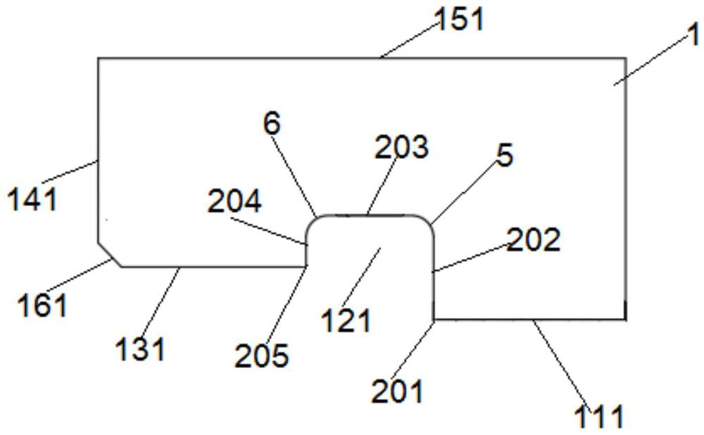
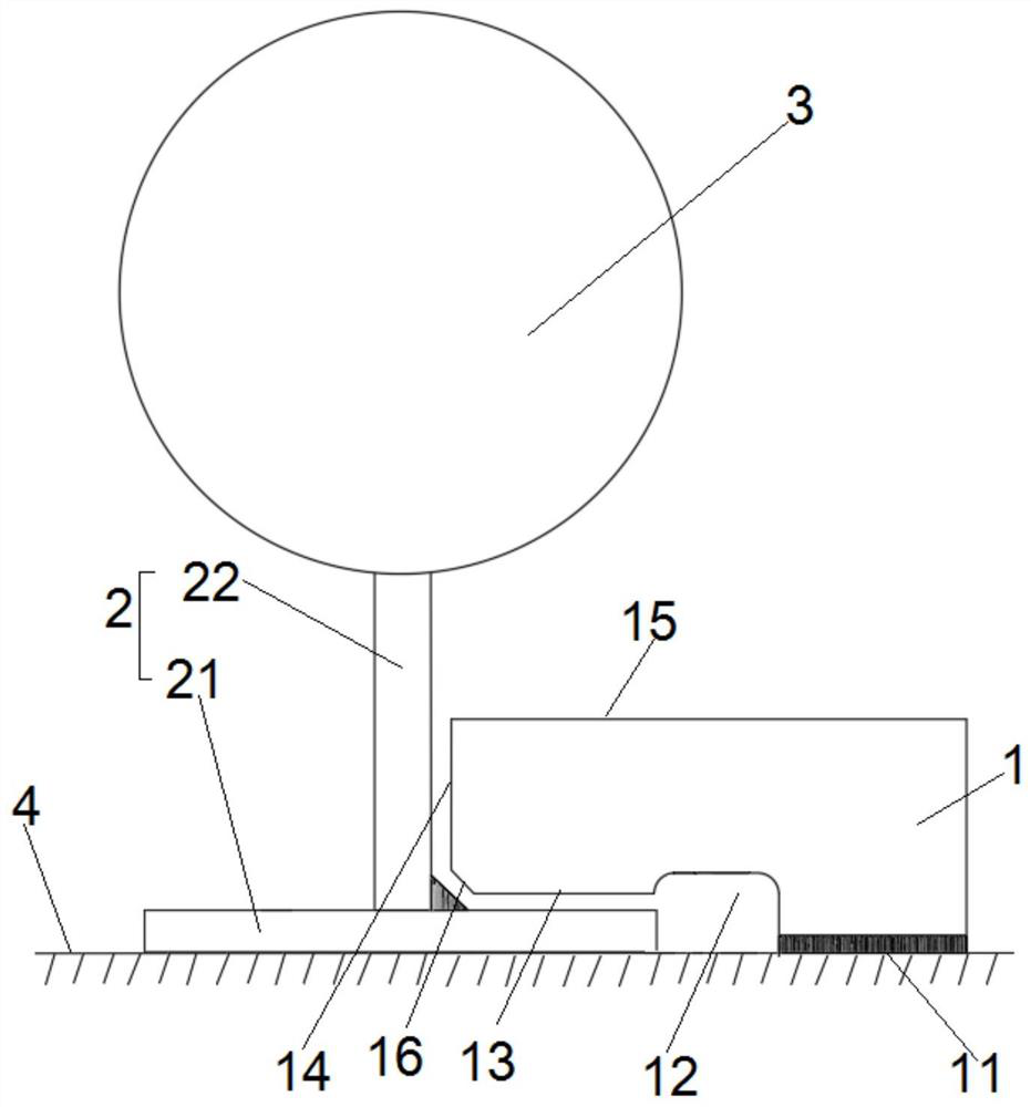
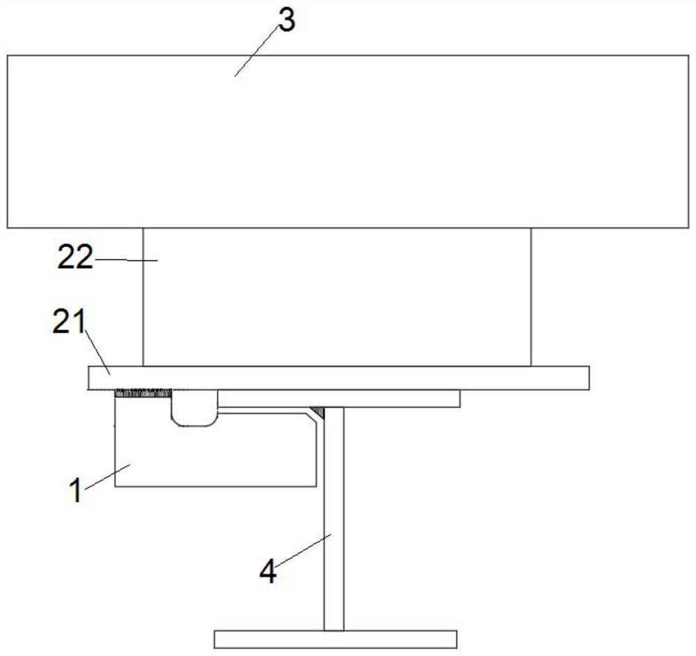
[0035] figure 1 It is a structural schematic diagram of a guiding and limiting block of the present invention, figure 2 It is a structural schematic diagram of Embodiment 1 of the present invention, such as figure 1 and figure 2 As shown, a guide limit block 1 for pipe shoes, pipe shoes 2 includes a bottom plate 21 and a support member 22 vertically connected to each other to form a T shape, the support member 22 is vertically fixed to the lower surface of the pipeline 3, and the bottom plate 21 is supported on the pipeline support On the platform 4, the guide and limit block 1 is located on the side of the bottom plate 21, and the guide and limit block 1 is integrally formed....


PUM


Abstract

The invention discloses a guide limiting block for a pipe shoe and an installation method of the guide limiting block. The contour of the cross section of the guide limiting block is in a trunk shape, and the guide limiting block comprises a connecting edge, an inwards-concave section, a guide edge, a limiting edge and an outer contour edge which are connected end to end in the clockwise direction; the connecting edge, the inwards-concave section, the guide edge, the limiting edge and the outer contour edge extend in the thickness direction to form a connecting face, an inwards-concave face, a guide face, a limiting face and an outer contour face respectively; the guide limiting block is of a trunk-shaped structure, the connecting face is used for fixing, the inwards-concave face enlarges the gap between the guide limiting block and a pipe shoe bottom plate, welding and coating are facilitated; the guide face and the limiting face are arranged to limit the movement direction of the pipe shoe bottom plate and a pipeline, the guide and limiting effects are achieved, installation is convenient, and the construction procedure is optimized; and by applying the guide limiting block, the problem of corrosion prevention dead corners of the guide limiting block of a pipe shoe of a process pipeline of an offshore oil platform is solved, potential engineering quality hazards can be effectively avoided, and the effects of reducing economic cost and facilitating installation are achieved.

Description

technical field [0001] The invention relates to the field of pipeline installation and construction, in particular to a guide limit block for pipe shoes and an installation method thereof. Background technique [0002] In the petrochemical industry, there are often a large number of densely arranged pipeline systems, including offshore oil production platforms. The pipeline system is complex and the layout space is limited. Insufficient dead corners that cannot be painted, the difficulty of anti-corrosion coating on the guide limit block of pipeline shoes, and the remaining quality problems of coating will bring great quality and safety risks to the subsequent pipeline operation and commissioning. [0003] In the traditional design, the guide limit block is usually designed as an angle steel or T-shaped steel guide limit form. The bottom plate and the pipeline support platform are clamped by the angle steel or T-shaped steel. Usually, the limit block needs to be installed fi...

Claims


Application Information

Patent Timeline
IPC IPC(8): F16L1/00F16L3/00F16L58/18
CPCF16L1/00F16L3/00F16L58/18
Inventor 杜光宋健代绪成赵刚左丰建雷俊杰史海峰程国东王秀鹏仲宇欣耿阳徐庚魏玉垒王论之宋文文
Owner OFFSHORE OIL ENG
Why Eureka
Try Eureka