
Optical fiber connector box convenient for optical fiber fusion welding

An optical fiber fusion splicing and splice box technology, which is applied to the coupling of optical waveguides, optics, optical guides, etc., can solve problems such as low efficiency, waste a lot of time to arrange and coil, and achieve the effect of increasing efficiency, convenient fixing method, and increasing fusion splicing efficiency.

Active Publication Date: 2021-09-07
SICHUAN TIANYI COMHEART TELECOM
View PDF22 Cites 0 Cited by
  • Summary
  • Abstract
  • Description
  • Claims
  • Application Information

AI Technical Summary

Problems solved by technology

[0002] The optical cable splice box is a connecting part that connects two or more optical cables together and has protective components. It must be used in the construction of optical cable lines and is one of the very important equipment. The optical fiber splice box in the prior art After the optical fiber is fused, the user needs to snap the heat-shrinkable tube into the slot on the splicing tray, and then coil the optical fiber on the splicing tray. Due to the large number of optical fibers, the user needs to spend a lot of time to arrange the winding, which is inefficient

Method used


Image

  • Optical fiber connector box convenient for optical fiber fusion welding
  • Optical fiber connector box convenient for optical fiber fusion welding
  • Optical fiber connector box convenient for optical fiber fusion welding

Examples


Embodiment Construction

[0025] The technical solutions of the present invention will be clearly and completely described below in conjunction with the accompanying drawings. Apparently, the described embodiments are some of the embodiments of the present invention, but not all of them. Based on the embodiments of the present invention, all other embodiments obtained by persons of ordinary skill in the art without making creative efforts belong to the protection scope of the present invention.

[0026] In the description of the present invention, it should be understood that the orientation or positional relationship indicated by the terms "upper", "lower", "front", "rear", "inner", "outer" etc. Orientation or positional relationship is only for the convenience of describing the present invention and simplifying the description, and does not indicate or imply that the referred device or element must have a specific orientation, be constructed and operated in a specific orientation, and thus should not ...


PUM


Abstract

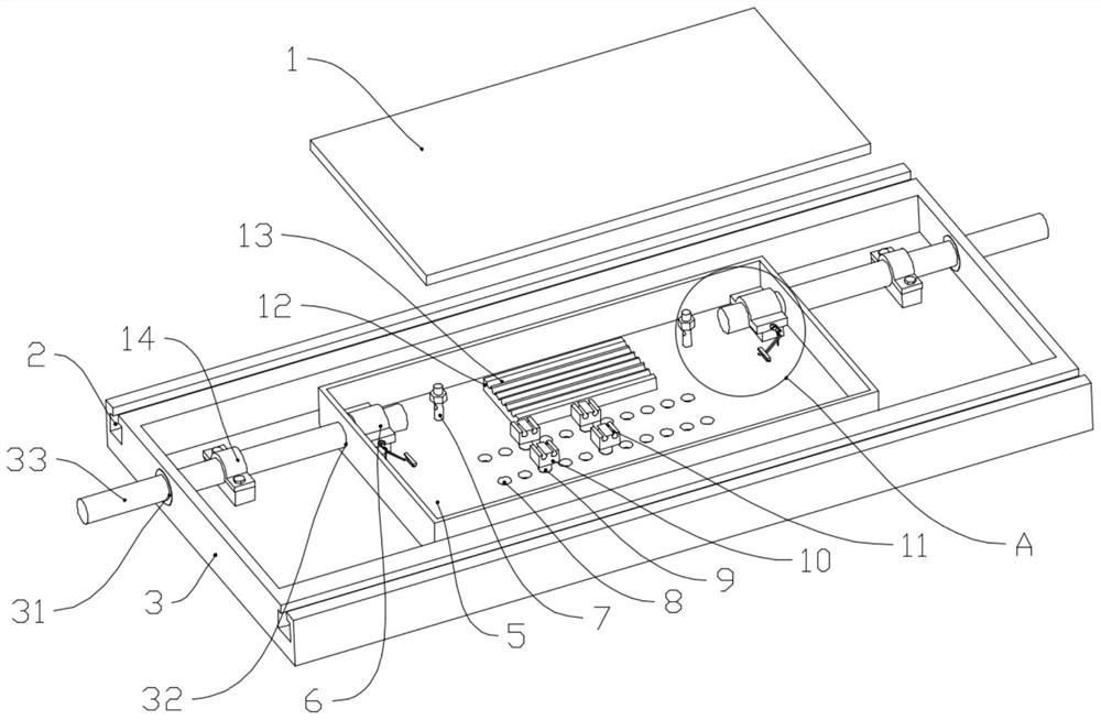
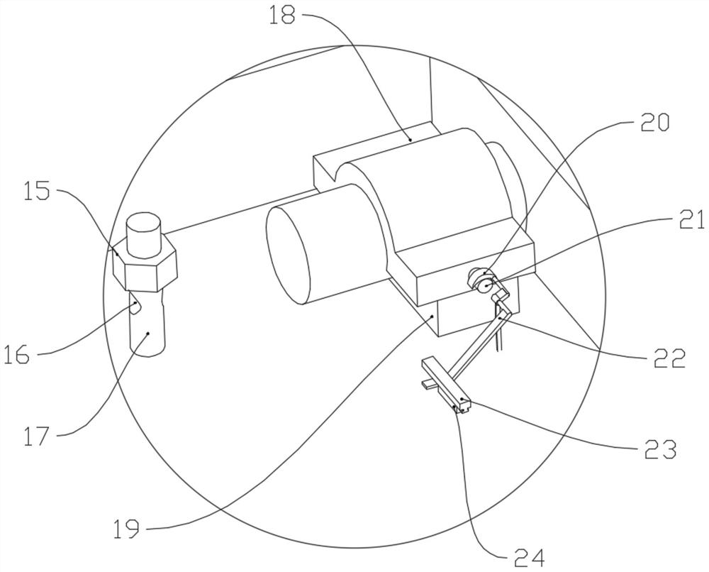
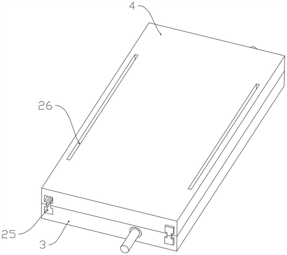
The invention discloses an optical fiber connector box convenient for optical fiber fusion welding, wherein the optical fiber connector box comprises a first box body and a first box body cover, and the first box body is internally provided with a winding component and a wire group fixing part; an insertion hole A is formed in the side wall of the first box body; the wire group fixing component is connected with the first box body; the winding component comprises a third box body, a third box cover and a clamping component, the third box body is arranged in the first box body, an insertion hole B is formed in the side wall of the third box body, the clamping component comprises an upper pressing buckle, a lower pressing buckle and a pressing component, and the lower pressing buckle is connected with the third box body; one side of the upper pressing buckle is hinged to the lower pressing buckle, and the other side of the upper pressing buckle is connected with the pressing component; the pressing component comprises an arc-shaped plate and a limiting component, the arc-shaped plate is in a semi-crescent shape and is connected with the third box body, and the rotating face of the arc-shaped plate is perpendicular to the rotating face of the upper pressing buckle; a cylindrical part is arranged on the upper pressing buckle, and the side wall of the cylindrical part abuts against the inwards-concave surface wall of the arc-shaped plate; and the limiting component is connected with the arc-shaped plate, and a clamping plate and a plurality of wire clamping parts are arranged in the third box body and used for fixing optical fibers.

Description

technical field [0001] The invention relates to the field of optical fiber splicing boxes, in particular to an optical fiber splicing box with convenient optical fiber fusion splicing. Background technique [0002] The optical cable splice box is a connecting part that connects two or more optical cables together and has protective components. It must be used in the construction of optical cable lines and is one of the very important equipment. The optical fiber splice box in the prior art After the optical fiber is fused, the user needs to snap the heat-shrinkable tube into the slot on the splicing tray, and then coil the optical fiber on the splicing tray. Due to the large number of optical fibers, the user needs to spend a lot of time to arrange the coiling, which is inefficient. Contents of the invention [0003] In view of the above-mentioned shortcomings of the prior art, the object of the present invention is to provide an optical fiber splice closure which is conve...

Claims


Application Information

Patent Timeline
Patent Type & Authority Applications(China)
IPC IPC(8): G02B6/38G02B6/255
CPCG02B6/38G02B6/2553
Inventor 王大才陈攀蓝鹏
Owner SICHUAN TIANYI COMHEART TELECOM
Learn More