3D hand-eye calibration method and device for mobile robot

A mobile robot, hand-eye calibration technology, applied in the directions of instruments, non-electric variable control, two-dimensional position/channel control, etc., can solve the problems that the existing technology cannot be applied, achieve the effect of suppressing amplification, and improve the calibration accuracy and stability. Effect

Pending Publication Date: 2021-09-07
上海仙工智能科技有限公司
View PDF1 Cites 7 Cited by
  • Summary
  • Abstract
  • Description
  • Claims
  • Application Information

AI Technical Summary

Problems solved by technology

[0005] However, this prior art is mainly applied to six-degree-of-freedom manipulators, so the robot needs to perform spatial rotation and translation in a specific way.
Although the calibration process is fully automatic, it requires the robot to have the ability to rotate in three degrees of freedom in space.
However, mobile robots such as AGVs and ARMs only have the ability to rotate with one degree of freedom in space, so the existing technology cannot be applied

Method used


Image

  • 3D hand-eye calibration method and device for mobile robot
  • 3D hand-eye calibration method and device for mobile robot
  • 3D hand-eye calibration method and device for mobile robot

Examples


Embodiment approach

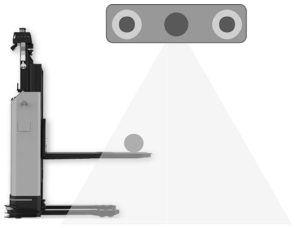
[0079] Such as Figure 1 to Figure 2 As shown, another aspect of the present invention also provides a mobile robot 3D hand-eye calibration method, in a preferred embodiment, the steps include:

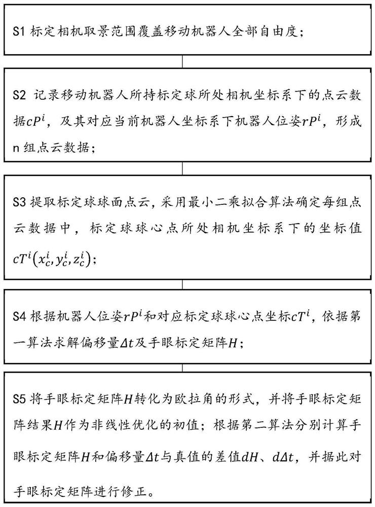
[0080] S1 calibrates the viewing range of the camera to cover all degrees of freedom of the mobile robot. In this embodiment, the calibration step includes:

[0081] 1) Fix the calibration ball on the robot actuator to ensure that there will be no displacement between the calibration ball and the robot during the calibration process.

[0082] 2) Adjust the robot to the field of view of the 3D camera to ensure that the 3D camera can capture the calibration ball.

[0083] 3) Move the robot within the field of view of the 3D camera, and record the pose information rP of the robot in the robot coordinate system during each movement, including the position and attitude rR i (R x , R y , R z ). At the same time, use the 3D camera to collect the point cloud data cP of the calibration...

experiment example

[0125] In order to describe the solution of the present invention more specifically, the implementation of the 3D hand-eye calibration of the mobile robot of the present invention will be described in detail below in conjunction with the accompanying drawings, taking an AGV forklift and a 3D camera as examples.

[0126] Without loss of generality, compared with the mechanical arm, the AGV forklift only has the ability to move in the three directions of X, Y, and Z and rotate around the Z axis. By introducing the application process of this method on the AGV forklift, it can be better explained The method has strong versatility.

[0127] At the same time, it is worth mentioning that the calibration method in this case abandons the traditional two-step algorithm, that is, first solve the offset between the calibration ball and the robot, and then solve the hand-eye calibration matrix, and use a one-step solution instead. Solve the calibration ball together with the robot's offse...


PUM


Abstract

The invention provides a 3D hand-eye calibration method and device for a mobile robot. The method comprises the following steps: S1, calibrating the view finding range of a camera to cover all degrees of freedom of the mobile robot; S2, recording point cloud data of a calibration ball held by the mobile robot in a camera coordinate system and a robot pose corresponding to the calibration ball in a current robot coordinate system to form n groups of point cloud data; S3, extracting the point cloud of the spherical surface of the calibration ball, and determining the coordinate value of the center point of the calibration ball in the camera coordinate system in each group of point cloud data by adopting a least square fitting algorithm; S4, solving offset and a hand-eye calibration matrix according to a first algorithm according to the pose of the robot and the coordinates of the center point of the corresponding calibration ball; and S5, converting the hand-eye calibration matrix into an Euler angle form, and taking a hand-eye calibration matrix result as an initial value of nonlinear optimization; and respectively calculating a hand-eye calibration matrix and a difference value between the offset and the truth value according to a second algorithm, and correcting the hand-eye calibration matrix according to the difference value. Therefore, the adaptation requirement for the degree of freedom of the robot is lowered, and the universality is improved.

Description

technical field [0001] The invention relates to the technical field of machine vision, in particular to a 3D hand-eye marking method and device applicable to at least one degree of freedom movement. Background technique [0002] As robot technology continues to penetrate into industrial and life scenarios, the production and use technologies of various single robots such as robotic arms, AGV cars, and ARMs are becoming more and more mature to meet the needs of different scenarios. As an actuator, these single robots can well replace people to complete some high-risk, repetitive and intensive work such as container transportation, logistics sorting and mechanical assembly. But robots, as terminal effectors, often do not have the ability to perceive. The 3D camera can obtain the three-dimensional information of the object, and has the ability to perceive the spatial position and posture of the object. In most work scenarios, robots often need 3D vision to provide guidance an...

Claims


Application Information

Patent Timeline
Patent Type & Authority Applications(China)
IPC IPC(8): G06T7/80G06T7/70G06F17/16G06F17/12G05D1/02
CPCG06T7/85G06T7/70G06F17/16G06F17/12G05D1/0219G06T2207/30244
Inventor 邓辉李华伟王益亮陈忠伟石岩
Owner 上海仙工智能科技有限公司
Why Eureka
Try Eureka