Road collapse wireless monitoring device and system thereof

A wireless monitoring device and road technology, applied in signal transmission systems, instruments, alarms, etc., can solve the problems of undetectable, increased pipeline and pipeline pressure, and reduced road pressure resistance.

Pending Publication Date: 2021-09-07
SHANGHAI ZENITECH ELECTRONICS TECH DEV
View PDF0 Cites 0 Cited by
  • Summary
  • Abstract
  • Description
  • Claims
  • Application Information

AI Technical Summary

Problems solved by technology

[0007] ①The road load is too heavy: the original design load can no longer meet the actual situation of the current traffic load, resulting in insufficient bearing capacity of the road surface, which is easy to cause road surface collapse;
[0008] ②Aging, cracking, water seepage and leakage of underground pipelines: long-term erosion of the soil foundation will lead to the loss of foundation soil, resulting in ground subsidence;
[0009] ③Extensive exploitation of groundwater: it will cause a lot of gaps in the rock formation caused by the lack of groundwater to be replenished too late, causing damage to the stratum structure, weakening the compressive load-bearing capacity of the foundation, and thus causing road surface collapse;
[0010] ④ Improper engineering construction: The construction of large underground buildings such as subways can make great use of underground space; while reducing the pressure on the ground surface, it can also damage the road foundation, reduce the pressure resistance of the road surface, and accelerate the road surface collaps...

Method used


Image

  • Road collapse wireless monitoring device and system thereof
  • Road collapse wireless monitoring device and system thereof
  • Road collapse wireless monitoring device and system thereof

Examples


Embodiment Construction

[0038] Embodiments of the present invention are described below through specific examples, and those skilled in the art can easily understand other advantages and effects of the present invention from the content disclosed in this specification. The present invention can also be implemented or applied through other different specific implementation modes, and various modifications or changes can be made to the details in this specification based on different viewpoints and applications without departing from the spirit of the present invention. It should be noted that, in the case of no conflict, the following embodiments and features in the embodiments can be combined with each other.

[0039]It should be noted that the diagrams provided in the following embodiments are only schematically illustrating the basic ideas of the present invention, and only the components related to the present invention are shown in the diagrams rather than the number, shape and shape of the compon...


PUM


Abstract

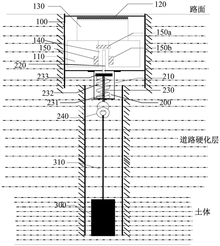
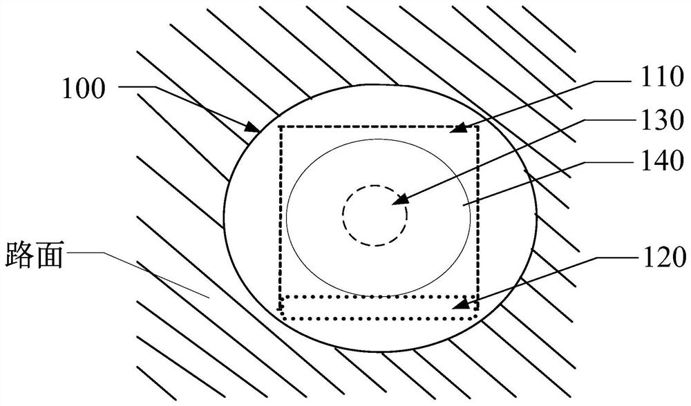
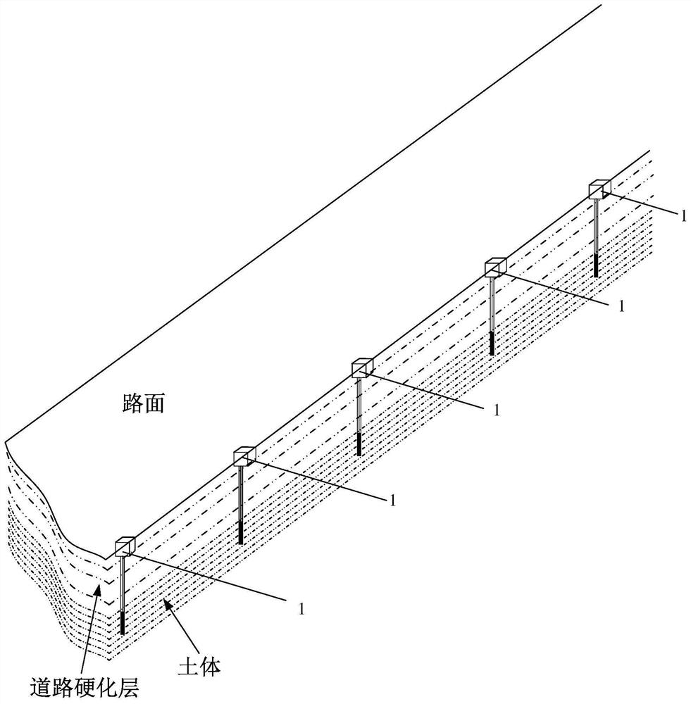
The invention provides a road collapse wireless monitoring device and system thereof, which are installed in a road surface body. The road collapse wireless monitoring device comprises a wireless monitoring main body which comprises a processor, a communication module, and a power supply unit, wherein a detection hole with a downward opening is formed in the wireless monitoring main body, and magnetoresistive sensors are arranged in the detection hole; each magnetoresistive sensor is electrically connected with the processor; a magnetic bar and a detection bar are arranged below the wireless monitoring main body; the upper end of the magnetic bar is inserted into the detection hole; and the lower end of the magnetic bar is connected with the detection bar embedded in the soil body, so that when the detection bar generates displacement due to the change of the soil body, the magnetic bar is driven to generate displacement in the detection hole relative to each magnetoresistive sensor, and the magnetoresistive sensors generate electric signals. Road collapse caused by cavities or lateral displacement of the soil body on the lower portion of the road can be monitored by the road collapse wireless monitoring device and system thereof in real time, and early warnings of different grades can be sent out in combination with the displacement degree; and the device is simple in equipment, low in power consumption, capable of continuously working for a long time after being installed, and convenient to manage and monitor.

Description

technical field [0001] The technical field of road collapse monitoring that the present application relates to, in particular, relates to a wireless road collapse monitoring device and a system thereof. Background technique [0002] Road subsidence is a geological phenomenon in which roads sink downward under the action of natural or human factors and form subsidence pits (holes) on the ground. Urban road subsidence not only increases the risk of traffic accidents and casualties, but also causes nearby building foundations to sink, houses to crack, underground pipelines to be damaged, urban flooding and storm surge disasters to aggravate, etc. [0003] In the context of rapid urban expansion, road subsidence accidents are frequent and frequent, and cases of heavy casualties and losses caused by road surface subsidence occur from time to time. The reasons for road subsidence are very complicated. According to the current statistics and analysis, the reasons for road subsiden...

Claims


Application Information

Patent Timeline
IPC IPC(8): G08C17/04G08B25/10
CPCG08C17/04G08B25/10
Inventor 高顺喜杨峰王喜超唐健清曹育兵何铁
Owner SHANGHAI ZENITECH ELECTRONICS TECH DEV
Why Eureka
Try Eureka