Electronic package and bearing structure thereof

A technology for electronic packages and load-carrying structures, which is applied in the direction of electrical components, electrical solid devices, circuits, etc., and can solve the problems that the stopper 18 is prone to overflowing glue, staining, and the area where the primer 14 cannot be filled, etc.

Pending Publication Date: 2021-09-07
SILICONWARE PRECISION IND CO LTD
View PDF0 Cites 1 Cited by
  • Summary
  • Abstract
  • Description
  • Claims
  • Application Information

AI Technical Summary

Problems solved by technology

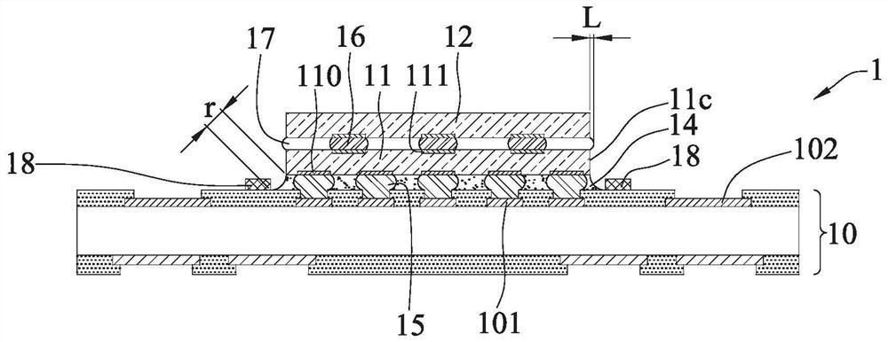
[0007] However, the thin film 17 will expand around due to being pressed by the second semiconductor element 12, and the protruding amount L protruding from the side 11c of the first semiconductor element 11 is about 440 micrometers (um), resulting in subsequent formation The glue-down position of the equipment of the primer 14 is too far away from the first semiconductor element 11, so that the pulling distance r (about 250um) between the primer 14 and the first semiconductor element 11 is too large, and the primer 14 cannot be filled. Fill the area between the packaging substrate 10 and the first semiconductor element 11
[0008] In addition, if the first semiconductor element 11 cannot pull the primer 14, the primer 14 will accumulate at the bottom glue, resulting in the problem of glue overflow at the stopper 18.
[0009] In addition, if the film 17 is used instead of the primer 14 to form between the packaging substrate 10 and the first semiconductor element 11, but the side of the packaging substrate 10 where the chip is mounted has highly densely arranged electrical contact pads 101 (or conductive bumps 15) on it, causing the primer 14 to fail to fill the gaps between the conductive bumps 15, resulting in air chambers (void) between the conductive bumps 15
[0010] On the other hand, if the primer 14 is formed first, and then the thin film 17 is formed, the position of the glue can be pulled closer to facilitate the first semiconductor element 11 to pull the primer 14 to fill the package substrate 10 and the first semiconductor. The area between the components 11, but the primer 14 is easy to crawl along the side 11c of the first semiconductor component 11 (siphon phenomenon) to the upper side of the first semiconductor component 11 when flowing, and contaminate the transfer of the upper side Pad 111, resulting in the subsequent failure of the second semiconductor element 12 to be effectively electrically connected to the first semiconductor element 11, for example, the electrode pad 111 is not stained with tin (Non-wetting) or is not connected to the conductive bump 16.

Method used


Image

  • Electronic package and bearing structure thereof
  • Electronic package and bearing structure thereof
  • Electronic package and bearing structure thereof

Examples


Embodiment Construction

[0065]The implementation of the present invention will be described below with reference to specific examples, and those skilled in the art can easily understand other advantages and effects of the present invention from the content disclosed in this specification.

[0066] It should be noted that the structures, proportions, sizes, etc. shown in the drawings attached to this specification are only used to match the content disclosed in the specification for the understanding and reading of those skilled in the art, and are not intended to limit the implementation of the present invention. Limiting conditions, so there is no technical substantive meaning, any modification of structure, change of proportional relationship or adjustment of size, without affecting the effect and purpose of the present invention, should still fall within the scope of the present invention. The disclosed technical content must be within the scope covered. At the same time, terms such as "above", "f...


PUM


Abstract

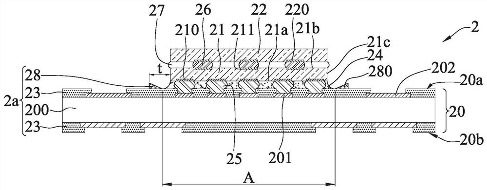
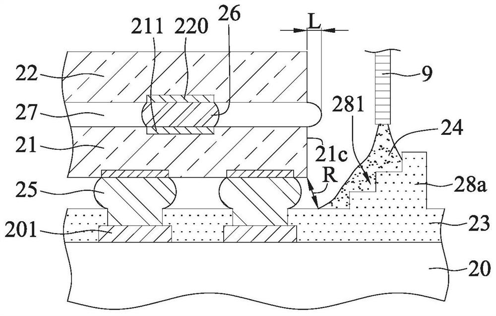
The invention relates to an electronic package and a bearing structure thereof. The electronic package comprises a bearing structure, an electronic component arranged on the bearing structure, and a packaging layer formed between the bearing structure and the electronic component. The bearing structure is provided with at least one guide piece with an inclined part. The design of the inclined part facilitates the formation of the packaging layer.

Description

technical field [0001] The invention relates to a packaging process, especially an electronic package and its supporting structure which is beneficial to the flip-chip packaging process. Background technique [0002] With the evolution of semiconductor packaging technology, different packaging types have been developed for semiconductor devices. In order to improve electrical functions and save packaging space, the industry has developed a stacked package structure to form a package stack structure (Package on Package (POP) packaging type, this type of packaging can take advantage of the heterogeneous integration characteristics of system in package (SiP), and can integrate electronic components with different functions, such as: memory, central processing unit, graphics processor, image application Processors, etc., achieve system integration through stacking design, and are suitable for various thin, light, short and small electronic products. [0003] figure 1 It is a s...

Claims


Application Information

Patent Timeline
Patent Type & Authority Applications(China)
IPC IPC(8): H01L23/31H01L23/13H01L25/00
CPCH01L23/3107H01L23/13H01L25/00
Inventor 林荣政陈汉宏周世民余国华
Owner SILICONWARE PRECISION IND CO LTD
Why Eureka
Try Eureka