
Method for controlling sliding nozzle device, and method for manufacturing slab

A technology of sliding nozzle and control method, which is applied in the direction of manufacturing tools, casting equipment, casting molten material containers, etc., and can solve the problems of inclusion generation and so on

Active Publication Date: 2021-09-07
JFE STEEL CORP
View PDF12 Cites 0 Cited by
  • Summary
  • Abstract
  • Description
  • Claims
  • Application Information

AI Technical Summary

Problems solved by technology

However, if oxygen cleaning is performed, there may be a problem of formation of inclusions due to the oxidation reaction of the metal in molten steel.

Method used


Image

  • Method for controlling sliding nozzle device, and method for manufacturing slab
  • Method for controlling sliding nozzle device, and method for manufacturing slab
  • Method for controlling sliding nozzle device, and method for manufacturing slab

Examples


Embodiment 1

[0068] Next, Example 1 performed by the inventors of the present application will be described. In the examples, casting was carried out using the method for manufacturing slabs according to the above-mentioned embodiment, and the success rate of opening holes in the recasting process, that is, the success rate of re-drilling was investigated.

[0069] In embodiment 1, the filling amount of using molten steel 4 is 190t, and the nozzle diameter of upper nozzle 2 is 70mm (nozzle sectional area 3.8×10 -3 m 2 ) of ladle 1 were investigated.

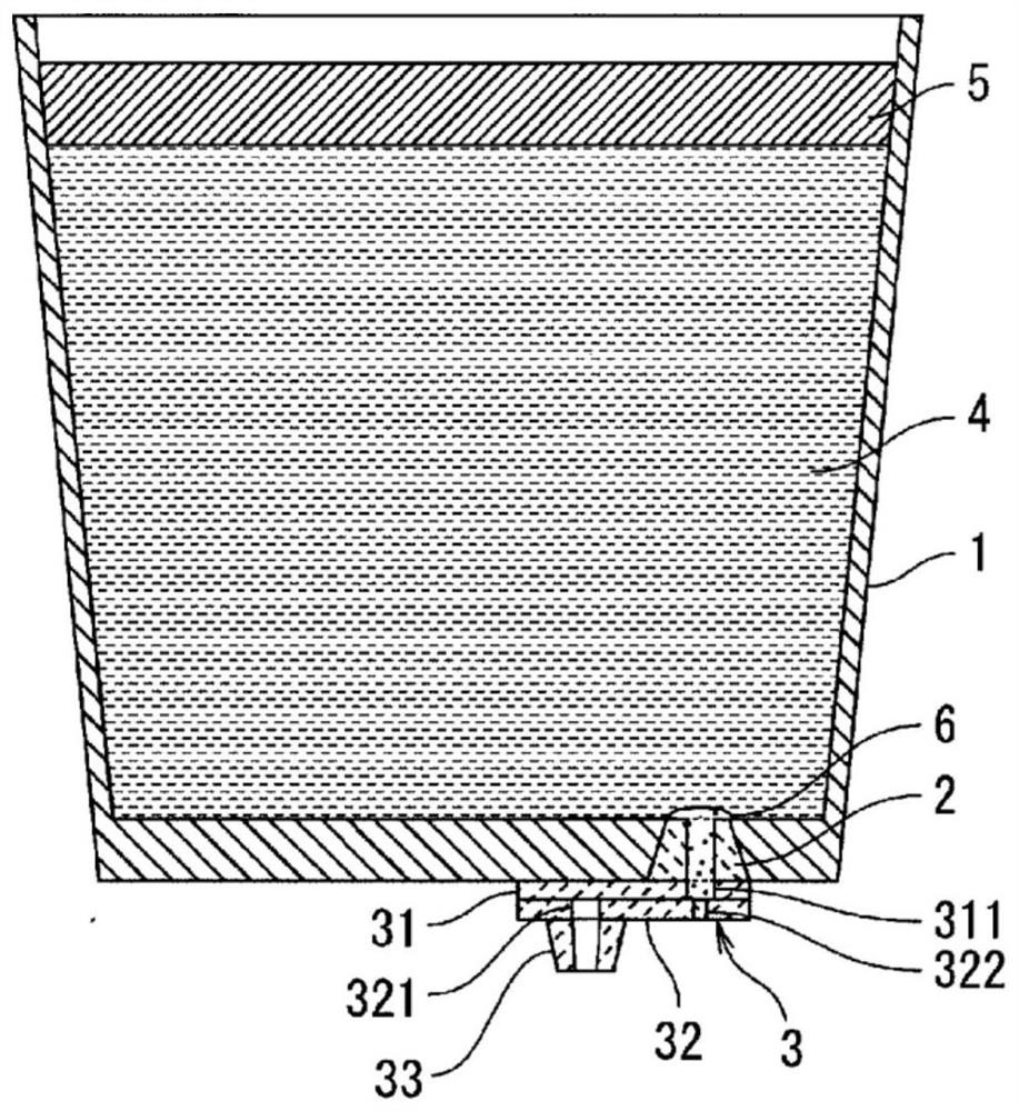
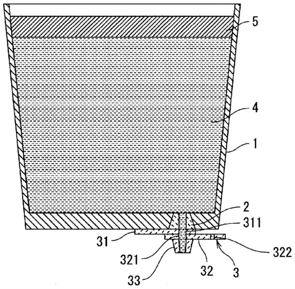
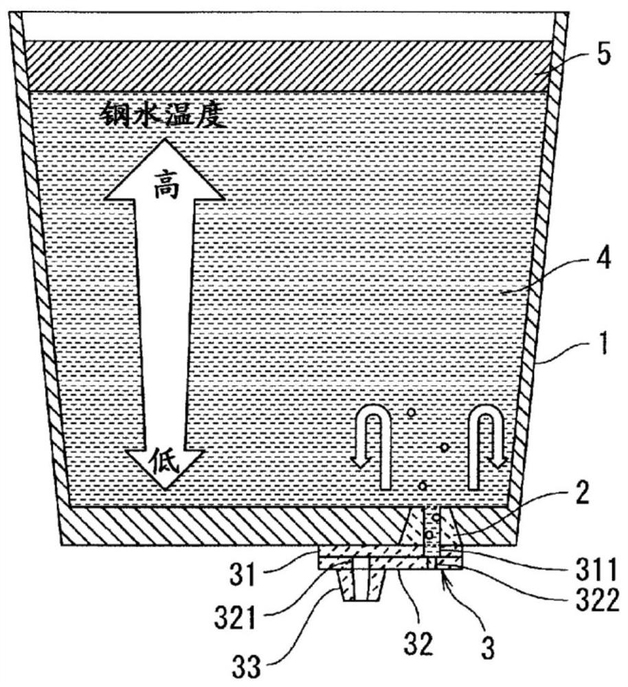
[0070] In Embodiment 1, in the pouring process, the sliding plate 32 is placed in the open position for 7 seconds, and the drainage sand and molten steel are poured out. Thereafter, the slide plate 32 is returned to the closed position, and Ar gas is blown into the molten steel 4 in the ladle 1 from the gas injection hole 322 through the first injection hole 311 . The flow rate of Ar gas is set to 30.0NL / min (7.8Nm 3 / (min·m 2 )).

[00...

Embodiment 2

[0074] In Example 2, before the investigation, the homogeneous mixing time under the conditions of the actual machine was calculated. As the calculation condition, the temperature T of molten steel 4 1 Set as 1827(K), the weight W of molten steel 4 is set as 190t, the blowing depth (bath depth) h v Set to 2.29m, set the atmospheric pressure P a Set to 0.1MPa, set the standard state temperature T 0 Set to 300K, set the bath diameter d v Set to 3.375m. Show the calculation results in Figure 7 . Such as Figure 7 As shown, it can be confirmed that 1 / 4 of the homogeneous mixing time is 61.0 s when the blowing flow rate of Ar gas under actual machine conditions is 30.0 NL / min.

[0075] Next, in Example 2, based on the above results, continuous casting of molten steel was performed with 1 / 4 of the homogeneous mixing time set to 61.0 s, and the success rate of re-drilling was investigated. It should be noted that in Example 2, the continuous casting of molten steel 4 was carri...


PUM


Abstract

Provided are a method for controlling a sliding nozzle device and a method for manufacturing a slab, with which it is possible to suppress the occurrence of a non-opening hole when molten steel in a ladle is to be re-poured. The method includes a gas blowing step in which, in a state in which molten steel (4) is accommodated in a ladle (1), a sliding plate (32) is set to an open position, and a portion of the molten steel (4) is poured out from the ladle (1) through a first nozzle hole (311) and a second nozzle hole (321), after which the sliding plate (32) is moved to a closed position and an inert gas is blown from a gas blowing hole (322) into the molten steel (4) in the ladle (1) through the first nozzle hole (311), and, after the gas blowing step, a re-pouring step in which the sliding plate (32) is set to the open position, and molten steel (4) is poured out from the ladle (1) through the first nozzle hole (311) and the second nozzle hole (321), wherein the amount of inert gas blown in in the gas blowing step is at least equal to 3.9 Nm<3> / (min.m<2>) and at most equal to 26.0 Nm<3> / (min.m<2>).

Description

technical field [0001] The present invention relates to a control method of a sliding nozzle device and a manufacturing method of a casting sheet. Background technique [0002] Molten steel (molten liquid) such as a tundish or a ladle used in the steelmaking process of a steel factory is held in a container, and a sliding nozzle device is provided at the bottom of the container in some cases. The sliding nozzle device installed at the bottom of the ladle is usually filled with drainage sand to prevent the molten steel from intruding into the nozzle hole and solidifying to prevent the hole from being opened until the pouring of molten steel such as pouring starts. Since this drainage sand causes the cleanliness to fall in the casting of high cleanliness steel, an operation method in which the drainage sand is once discharged and then cast is performed in some cases. In such an operation method, in a state where the ladle is arranged at the drainage sand discharge position, t...

Claims


Application Information

Patent Timeline
Patent Type & Authority Applications(China)
IPC IPC(8): B22D11/10B22D41/42B22D11/18
CPCB22D41/22B22D11/10B22D41/42B22D11/18
Inventor 三原亮祐熊谷笃长谷川贵士渡边佑介山内崇上原博英
Owner JFE STEEL CORP
Learn More