
Rapid press-fitting locking mechanism

A technology of locking mechanism and pressing mechanism, applied in workpiece clamping devices, manufacturing tools, etc., can solve the problems of reduced economic benefits, loose workpieces, low work efficiency, etc.

Pending Publication Date: 2021-09-10
YONGKANG LINGYING ELECTRICAL APPLIANCES
View PDF6 Cites 0 Cited by
  • Summary
  • Abstract
  • Description
  • Claims
  • Application Information

AI Technical Summary

Problems solved by technology

[0003] However, the pressing force of the traditional pressing mechanism is not strong, it is easy to cause the workpiece to loosen during operation, and the operating efficiency is low, which reduces the economic benefit

Method used


Image

  • Rapid press-fitting locking mechanism
  • Rapid press-fitting locking mechanism
  • Rapid press-fitting locking mechanism

Examples


Embodiment 1

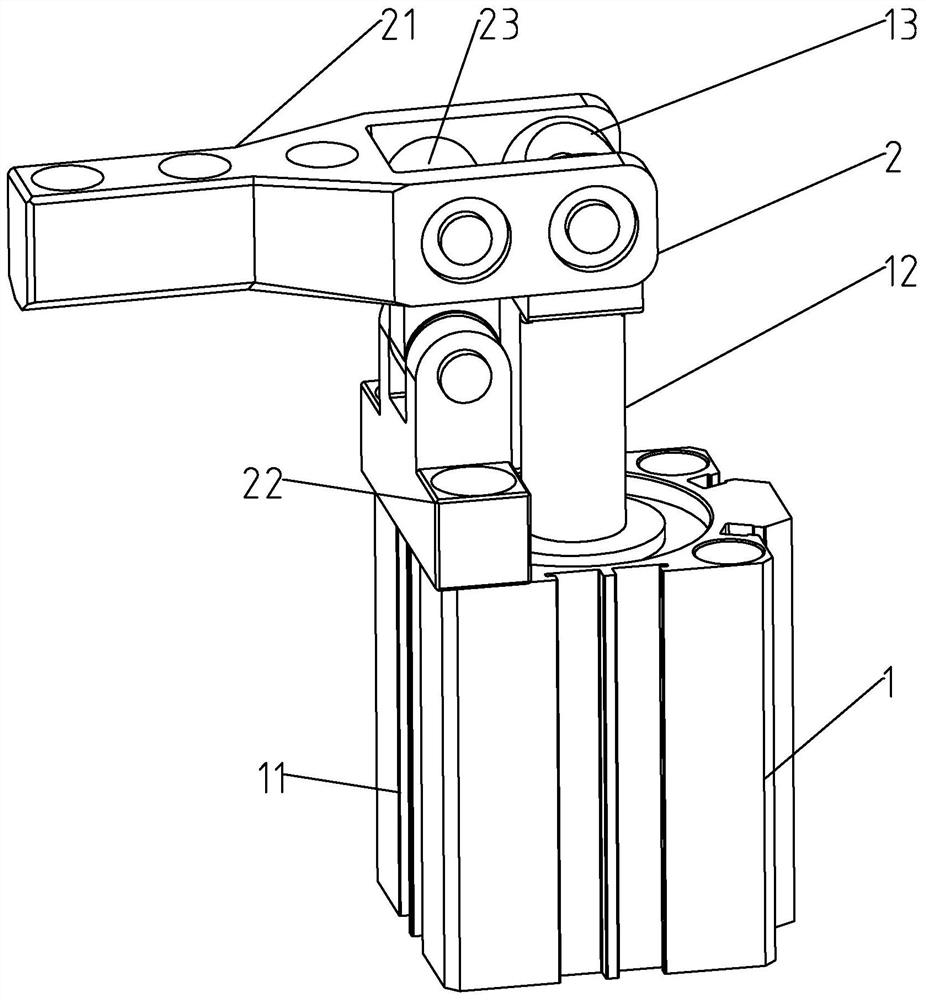
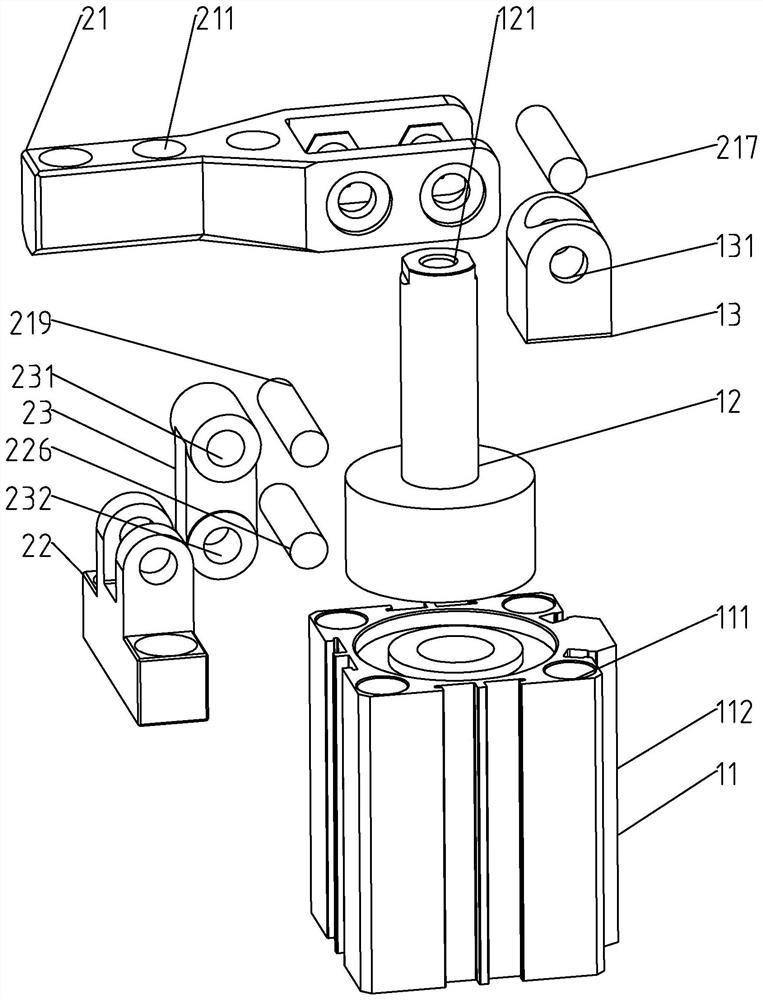
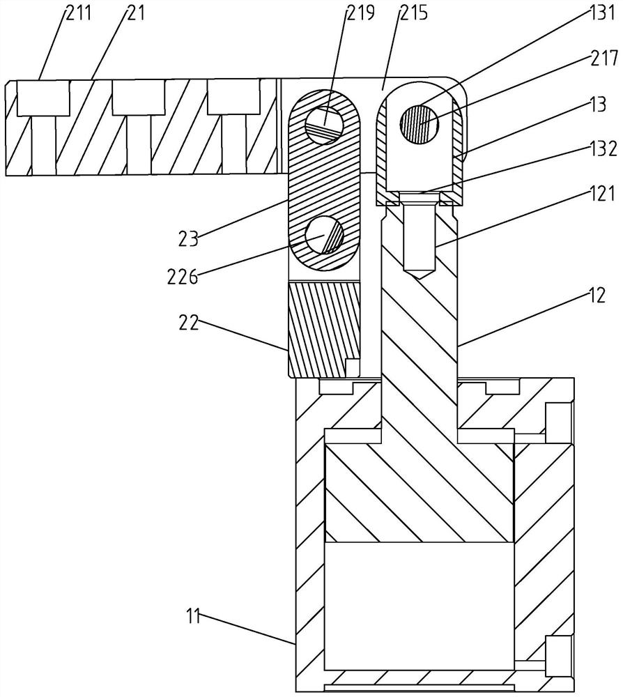
[0036] Such as figure 1 , figure 2 As shown, the present invention provides a technical solution, a fast press-fit locking mechanism, which is composed of a driving device 1 and a pressing mechanism 2. The driving device 1 includes a cylinder 11 and a piston rod 12, and one end of the piston rod 12 is located at Inside the cylinder 11, the other end stretches out from the top of the cylinder 11, and the top outer surface of the piston rod 12 is fixedly connected with a connecting pin 13; The seat 22 is fixedly installed on the top of the cylinder 11, and the mounting seat 22 is movably connected with the middle part of the compression rod 21 through the hinge arm 23, and the piston rod 12 is movably connected with the end of the compression rod 21 adjacent to the end of the cylinder 11 through the connecting pin 13. The end of the pressing rod 21 away from the connecting pin 13 is also provided with several positioning holes 211 .

[0037] The above-mentioned fast press-fit...

Embodiment 2

[0039] Such as figure 1 As shown, the present invention provides another technical solution, a quick press-fit locking mechanism, which is composed of a driving device 1 and a pressing mechanism 2 .

[0040] Such as image 3 , 4 As shown, the driving device 1 is composed of a cylinder 11 and a piston rod 12. The piston rod 12 is provided with one end of the piston located inside the cylinder 11, and the other end stretches out from the top of the cylinder 11. The pressure energy of the compressed gas in the cylinder 11 can be converted into a piston The mechanical energy of motion, and the top outer surface of piston rod 12 is fixedly connected with connecting pin 13; Figure 10 As shown, the connecting pin 13 is provided with a first mounting hole 132, and the top of the piston rod 12 is provided with a first threaded hole 121. The locking bolt (not shown in the figure) in the fixed connection. The piston rod 12 works through the cylinder 11 to drive one end of the compre...


PUM


Abstract

The invention relates to a rapid press-fitting locking mechanism which comprises a driving device and a pressing mechanism. The driving device comprises an air cylinder and a piston rod, one end of the piston rod is located in the air cylinder, the other end of the piston rod extends out of the top of the air cylinder, and the outer surface of the top of the piston rod is fixedly connected with a connecting pin; and the pressing mechanism comprises a pressing rod, a mounting seat and a hinge arm, the mounting seat is fixedly mounted at the top of the air cylinder and movably connected with the middle of the pressing rod through the hinge arm, the piston rod is movably connected with the end, close to the air cylinder, of the pressing rod through the connecting pin, and a plurality of positioning holes are formed in the end, away from the connecting pin, of the pressing rod. The rapid press-fitting locking mechanism has the beneficial effects that the pressing force is improved, the operation accuracy is improved, and the operation efficiency is improved.

Description

technical field [0001] The invention relates to a press-fit locking device, in particular to a quick press-fit locking mechanism, which belongs to the technical field of mechanical devices. Background technique [0002] In industries such as vehicles, electronic manufacturing, and mechanical processing, there are quite a lot of equipment that need to clamp and position the processed workpieces and products. Clamping is an important part of the workpiece clamping process. After the workpiece is positioned, it must pass through the clamping mechanism. Generate clamping force, press the workpiece on the positioning element to ensure accurate positioning position, and will not be caused by cutting force, workpiece gravity, centrifugal force, inertial force, and external pressure from different directions during workpiece processing. Position changes and vibrations are used to ensure machining accuracy and safe operation. [0003] However, the pressing force of the traditional p...

Claims


Application Information

Patent Timeline
IPC IPC(8): B25B11/00
CPCB25B11/00
Inventor 徐江正
Owner YONGKANG LINGYING ELECTRICAL APPLIANCES
Learn More