Cable raw material cutting, winding and rolling full-automatic production equipment
A production equipment, fully automatic technology, applied in the direction of conveying filamentous materials, thin material handling, transportation and packaging, etc., can solve the problems of labor consumption, slow work efficiency, and high economic costs
- Summary
- Abstract
- Description
- Claims
- Application Information
AI Technical Summary
Problems solved by technology
Method used
Image
Examples
Embodiment 1
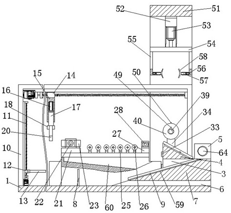
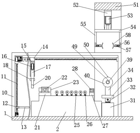
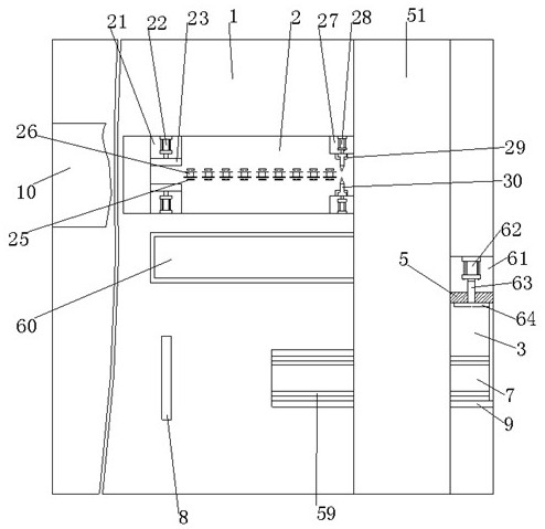
[0052] refer to Figure 1-11 , is a structural schematic diagram of Embodiment 1 of the present invention, a kind of automatic production equipment for cutting, winding and winding cable raw materials, including a base plate 1, a pad 2 is installed on the base 1, and an intelligent mobile device is installed on the base 2 jacking mechanism;
[0053] Wipe the supporting sliding structure, the fixed supporting structure is fixed on the base plate 1 and located under the intelligent mobile jacking mechanism;
[0054] Intelligent cutting structure, the intelligent cutting structure is fixed on the pad 2 and is located on both sides of the fixed support structure;
[0055] An intelligent mobile winding mechanism, the intelligent mobile winding mechanism is fixed on the substrate 1 and is located on the side of the platform 2;
[0056] An intelligent mobile retrieving and inserting mechanism, the intelligent mobile retrieving and inserting mechanism is fixed on the base plate 1 an...
Embodiment 2
[0067] refer to Figure 1-10 , the difference of this embodiment is that: the intelligent mobile jacking mechanism includes a fixed frame 10, a first straight pin screw module 11, a connecting plate 12, two struts 13 and a traction structure;
[0068] The fixing frame 10 is fixed on the base plate 1 and located above the base 2, the first straight pin screw module 11 is fixed on the side wall of one of the legs of the fixing frame 10, and the connecting plate 12 is fixed on the first straight pin On the moving end of the screw module 11, the two struts 13 are fixed on the side wall of the connecting plate 12, and the traction structure is fixed on the lower wall of the beam of the fixing frame 10;
[0069] In actual use: the staff will reasonably place the cable raw materials that need to be wound on the two support rods 13, and put one end of the cable raw materials on the pad 2. The matched programmable controller performs the control operation, and the driving end of the f...
Embodiment 3
[0071] refer to Figure 1-10 , the difference of this embodiment is that the traction structure includes the second direct pin screw module 14, the installation rod 15, the first electric push rod 16, the reinforcement column 17, the assembly plate 18, two second electric push rods rod 19 and two cable clamps 20;
[0072] The second direct pin screw module 14 is fixed on the lower wall surface of the beam of the fixed frame 10, the installation rod 15 is detachably connected to the moving end of the second direct pin screw module 14, and the first electric push rod 16 is embedded Installed in the lower wall of the installation rod 15, the reinforcement column 17 is detachably connected to the telescopic end of the first electric push rod 16 and located in the installation rod 15, and the assembly plate 18 is detachably connected to the lower end surface of the reinforcement column 17, The two second electric push rods 19 are respectively embedded in the two side walls of the ...
PUM
 Abstract
Description
Claims
Application Information
 - R&D
- Intellectual Property
- Life Sciences
- Materials
- Tech Scout
- Unparalleled Data Quality
- Higher Quality Content
- 60% Fewer Hallucinations
Browse by: Latest US Patents, China's latest patents, Technical Efficacy Thesaurus, Application Domain, Technology Topic, Popular Technical Reports.
© 2025 PatSnap. All rights reserved.Legal|Privacy policy|Modern Slavery Act Transparency Statement|Sitemap|About US| Contact US: help@patsnap.com


