Vertical combustor system capable of ascending and descending and application method thereof

A burner and vertical technology, which is applied in the direction of crucible furnaces, furnaces, charging treatment types, etc., can solve the problems of deterioration of furnace conditions, metal phase stagnation and non-flow, and low metal content, so as to solve the problem of deadening and improve recovery rate Effect

Pending Publication Date: 2019-09-20
CINF ENG CO LTD
View PDF0 Cites 0 Cited by
  • Summary
  • Abstract
  • Description
  • Claims
  • Application Information

AI Technical Summary

Problems solved by technology

[0004] 1. The melt located under the burner is relatively static, so that the mass transfer and heat transfer efficiency of the melt below is very low. The heat of the metal phase mainly depends on the liquid metal generated by the reaction and the heat conduction transfer of the melt. The metal production speed And the thermal conductivity of the melt directly determines how much heat the metal phase gets, thus determining the temperature of the metal phase
[0005] 2. It is easy to form a highly viscous diaphragm layer at the height of the phase interface. The main component of the diaphragm layer is metal oxide, which affects the generated liquid metal and moves down into the metal phase, resulting in the deterioration of the furnace condition.
And because the metal content is low, the thermal conductivity of the melt is poor, so that the temperature at the bottom of the molten pool is low, so that the metal phase at the bottom of the molten pool is likely to be stuck and not flow. The applicant has taken many measures for this in the past, such as reducing The depth of molten pool; adopting high and low hearth structure; adopting high and low nozzle layout, etc., but these measures have not fundamentally solved this problem

Method used


Image

  • Vertical combustor system capable of ascending and descending and application method thereof
  • Vertical combustor system capable of ascending and descending and application method thereof
  • Vertical combustor system capable of ascending and descending and application method thereof

Examples


Embodiment Construction

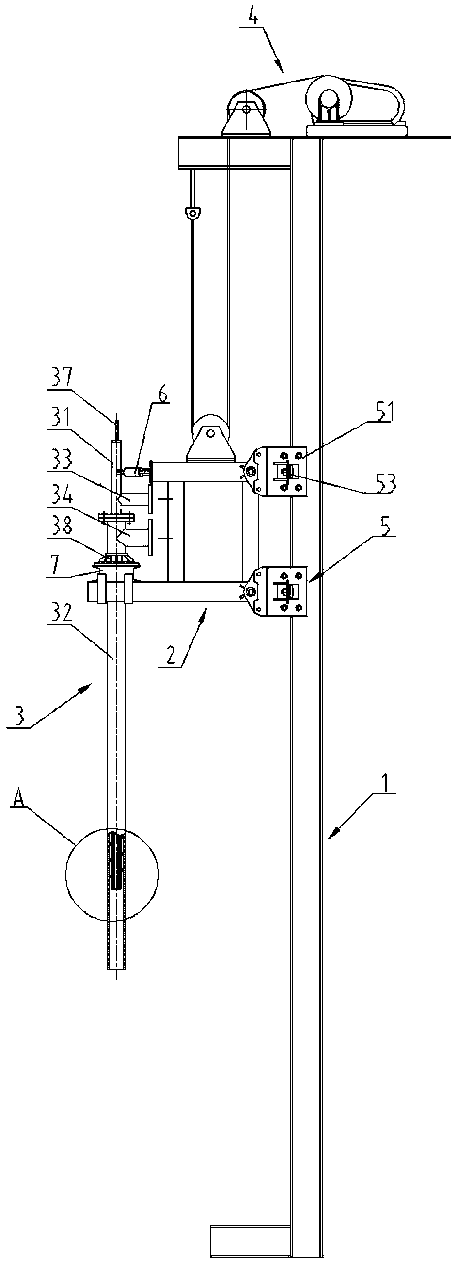
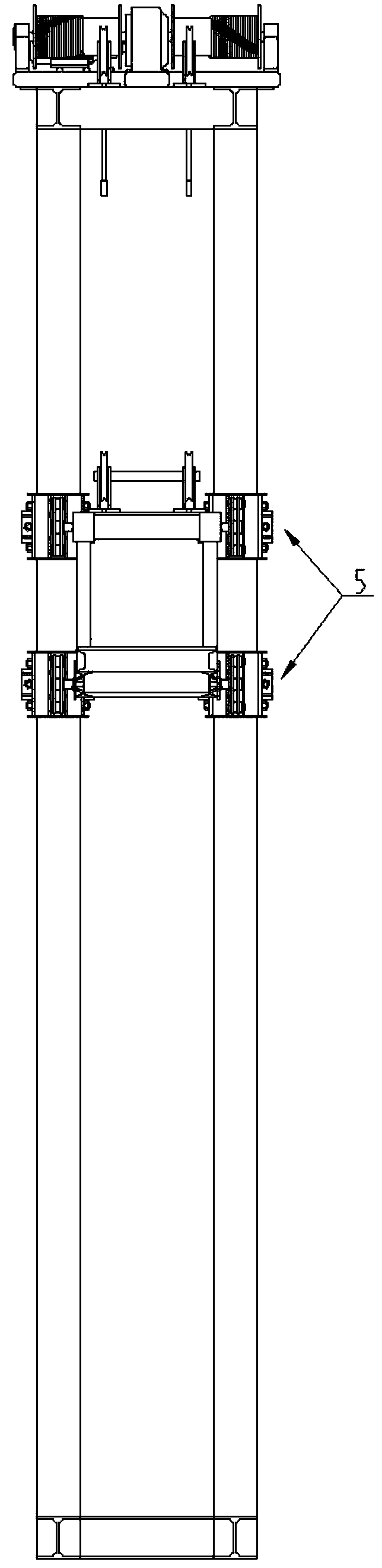
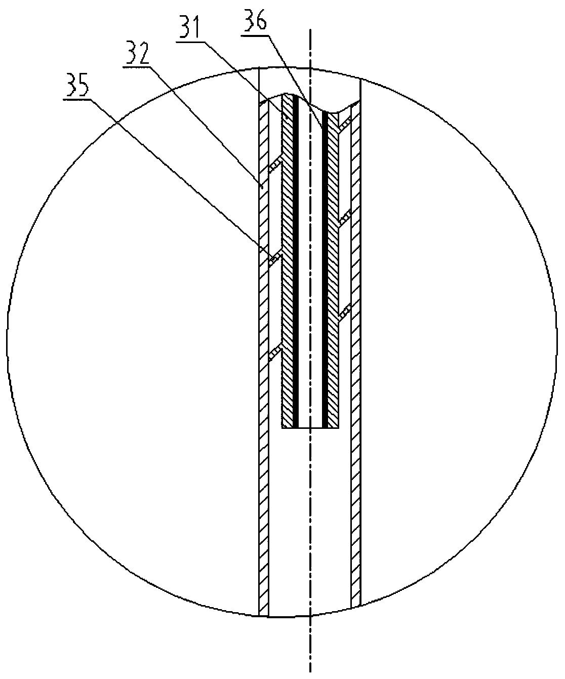
[0029] combine Figure 1 to Figure 4 It can be seen that the liftable vertical burner system disclosed in this embodiment and its application method include a lift rail 1 , a lift frame 2 , a burner 3 , a lift drive device 4 , and a guide wheel device 5 .

[0030] The lifting track 1 of the present embodiment includes two H-shaped steels arranged in parallel vertically and a horizontal connecting frame between the bottom and the top of the H-shaped steels, and the H-shaped steels are used as the running track of the lifting frame.

[0031] The lifting frame 2 of the present embodiment comprises a rectangular top frame and a bottom frame arranged in parallel and a connecting beam between the two. Both ends of the inner side of the frame are respectively symmetrically connected with guide wheel devices 5 . A lifting frame is equipped with four sets of guide wheel devices to ensure that the lifting frame maintains vertical lifting during the lifting process without deviation and...


PUM


Abstract

The invention discloses a vertical combustor system capable of ascending and descending and an application method of the vertical combustor system capable of ascending and descending. The vertical combustor system capable of ascending and descending comprises a lifting rail, a lifting frame, a combustor and a lifting drive device. A power device of the lifting drive device is fixed to the top of the lifting rail. The lifting frame is connected to the lower end of an action executor of the lifting drive device. Guide wheel devices are connected to one side of the lifting frame. The combustor is fixed to the opposite side of the side connected with the guide wheel devices. A lifting power device works to drive the lifting frame to slide vertically along the lifting rail through the guide wheel devices, so that vertical position change of the combustor is achieved. The heat demands at different heights in different areas of the bottom of a melt can be met by selecting different positions and different insertion depths of the combustor according to needs. The stagnation problem of a metal phase can be solved, and an isolation membrane layer between the metal phase and a slag phase of the melt can be eliminated, a metallic oxide is reduced into metal, the metal enters the metal phase to flow into a clarification separation area of a smelting furnace, metal carried away by slag is reduced, and the recovery rate of the heavy metal is improved. Meanwhile, harmless treatment is conducted on heavy metal solid waste.

Description

technical field [0001] The invention relates to the field of metallurgical heat energy equipment, in particular to a liftable vertical burner system and an application method thereof. Background technique [0002] For rectangular molten pool melting furnaces, burners or nozzles are generally fixedly installed on both sides of the furnace body, while for circular melting furnaces, burners or nozzles are generally fixedly installed around the furnace body, and the installation height is at the slag level. The middle and lower part of the layer is about 200-300mm higher than the metal-slag phase interface. Oxygen-enriched air, fuel or reducing agent are generally sprayed horizontally into the slag layer of the melt, and burn in the slag layer to form agitation. [0003] However, the applicant has verified through experiments that the above-mentioned installation method of the burner or the nozzle has the following two problems: [0004] 1. The melt located under the burner is...

Claims


Application Information

Patent Timeline
Patent Type & Authority Applications(China)
IPC IPC(8): F27B14/14F27D99/00
CPCF27B14/143F27D99/0033F27D2099/004F27M2003/13
Inventor 张乐如张岭杜磊
Owner CINF ENG CO LTD
Why Eureka
Try Eureka