Windproof high-rise steel structure vertical correction device

A correction device and steel structure technology, applied in building construction, processing of building materials, measuring fixed angles, etc., can solve problems such as large errors, complicated loading and unloading, and complicated measurement operations

Inactive Publication Date: 2021-09-10
武汉合创四联科技发展有限公司
View PDF1 Cites 4 Cited by
  • Summary
  • Abstract
  • Description
  • Claims
  • Application Information

AI Technical Summary

Problems solved by technology

[0004] Although the overall device has achieved the vertical correction of the column, the method of measuring through the scale not only has a relatively large error, but also the measurement operation is relatively co

Method used


Image

  • Windproof high-rise steel structure vertical correction device
  • Windproof high-rise steel structure vertical correction device
  • Windproof high-rise steel structure vertical correction device

Examples


Embodiment 1

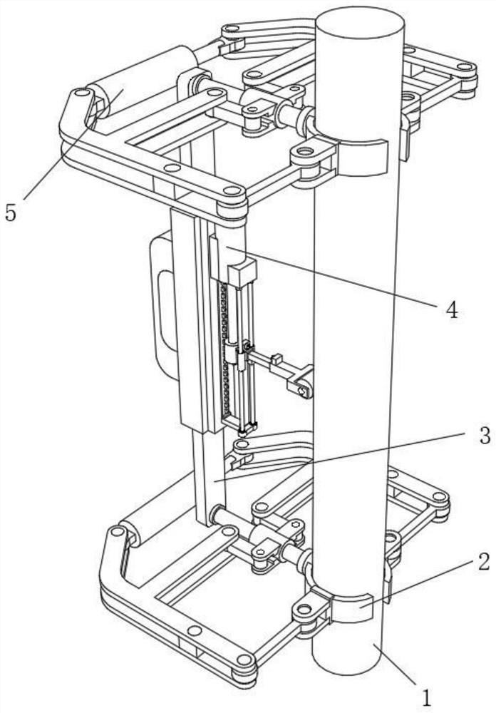
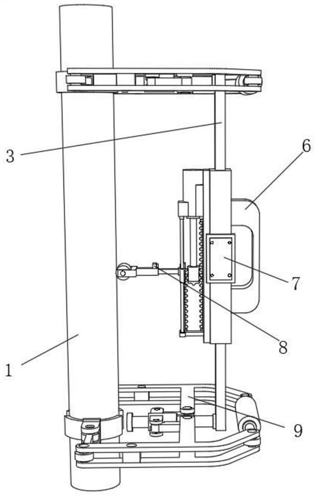
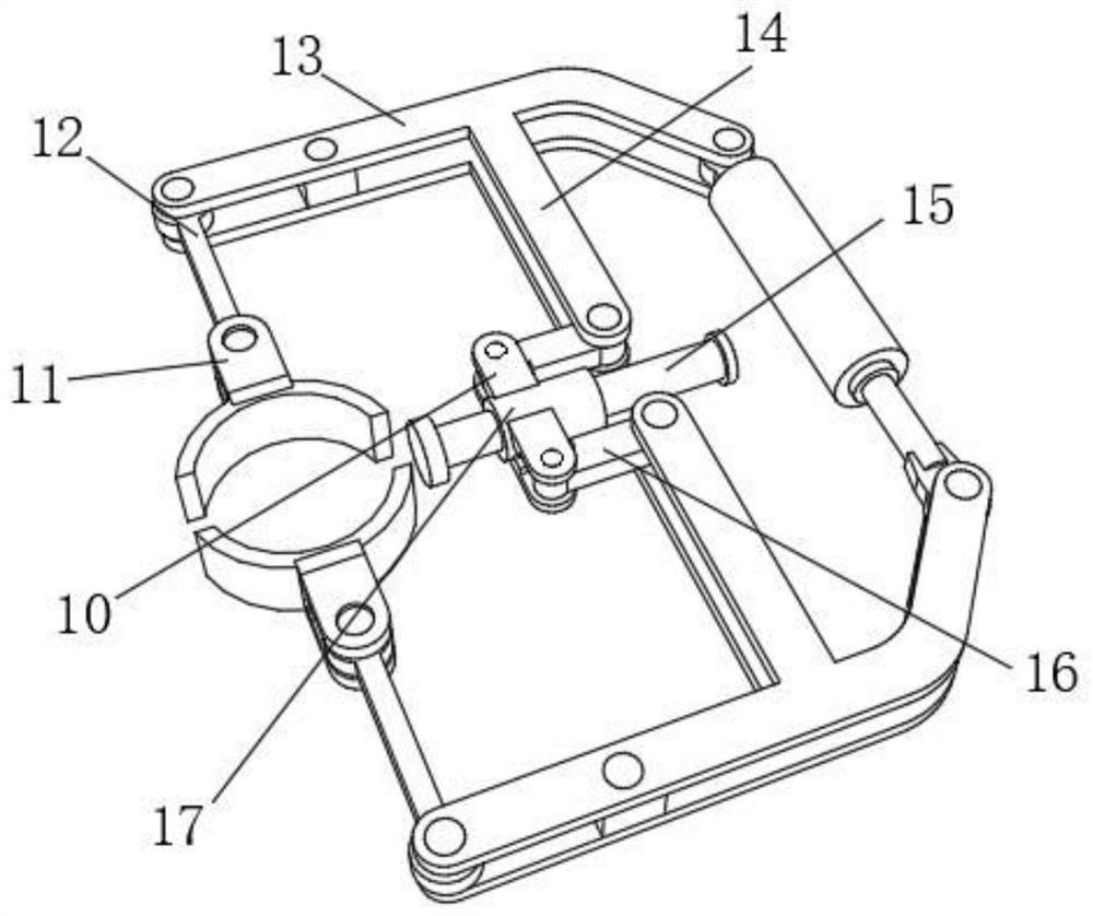
[0033] A wind-resistant high-rise steel structure vertical correction device, such as Figure 1-4 As shown, two clamping mechanism 9, two of the clamping mechanism 9 outputs two card ring 2 by bolts, and four snaps 2 cards have the same steel column 1, two clamping The partially retractable rod 3 is fixed to the side of the mechanism 9, and the end portion of the telescopic rod 3 is provided with a verticality rolling measuring mechanism, the output end of the verticality rolling measuring mechanism is provided with a roller 23, vertically rolling measuring mechanism. On the side, the distance sensor 8 is fixed by the bolt, and the outer wall of the retracting rod 3 is fixed by the bolt, and the outer wall of the telescoping rod 3 is fixed by the bolt 7.

[0034] When the handle 6 is operated by the handle 6 causes the designated position, and the card ring 2 is brought into the top end and the bottom end of the steel column 1 by starting the two clamping mechanism 9, the verticali...

Embodiment 2

[0041] A wind-resistant high-rise steel structure vertical correction device, such as Figure 5 As shown, in order to facilitate the steel structural sheet; the present embodiment, the following improvements are made on the basis of the first embodiment: the roller 23 can be replaced with a support plate 25, and the outer walls of the support plate 25 have a weld groove, and The inner wall of each weld groove is welded to have a fixing cylinder 26, and each fixing tube 26 has a finite ring 27, and four rollers 24 are fixed by the support plate 25; the support will be supported by the limit ring 27. The plate 25 is fixed to the top end of the telescopic bracket 22 and causes the four rollers 24 of the support plate 25 against the steel structural sheet, and the two rollers 24 are moved along the steel sheet, which not only avoids the support plate 25 in the steel sheet. Direct contact friction and ensure the stability of the measurement.


PUM


Abstract

The invention discloses a windproof high-rise steel structure vertical correction device, and relates to the technical field of high-rise steel structure vertical correction. The problem of measurement efficiency is solved. The device specifically comprises two clamping mechanisms, the output ends of the two clamping mechanisms are provided with two clamping rings, the four clamping rings are connected with the same steel column in a clamped mode, the opposite sides of the two clamping mechanisms are provided with the same telescopic rod, the end of one side of the telescopic rod is provided with a perpendicularity rolling measuring mechanism, the outer wall of the back face of the telescopic rod is provided with a handle, a display screen is arranged on the outer wall of one side of the telescopic rod, each clamping mechanism comprises a second air cylinder, two fixing blocks, two clamping blocks, two first guide rods, two L-shaped supporting rods, two connecting rods, a fixing shaft, two second guide rods and a sliding sleeve, and one end of each fixing shaft is arranged at one end of the corresponding telescopic rod. According to the device, a measurer can quickly obtain a perpendicularity measurement result, the steel column measurement efficiency and quality are improved, and carrying and operation are convenient.

Description

Technical field [0001] The present invention relates to the field of high-rise steel structures, and more particularly to a wind-resistant high-rise steel structure vertical correction device. Background technique [0002] The high-rise steel structure generally refers to a six-layer or more or more, mainly used steel, steel plate connection or welding into a member, which is connected, welded, and welded steel frame structures, steel frame - concrete core cartridges In the form of structure, the latter is more widely used in modern high-rise and ultra-high-rise steel structures. In fact, it belongs to steel concrete mixed structures. In the construction of high-rise steel structures, the steel structure needs to be perpendicularly corrected. [0003] According to the search, the Chinese patent application number is a patent of CN202020161228.x, which discloses a vertical correction device of a column stent, including a lower base, and a single shaft driver is attached to the lef...

Claims


Application Information

Patent Timeline
IPC IPC(8): E04G21/18G01C15/12
CPCE04G21/1841G01C15/12
Inventor 王帆
Owner 武汉合创四联科技发展有限公司
Why Eureka
Try Eureka