
Manufacturing method of LED display module

A manufacturing method and display module technology, applied to electrical components, electric solid devices, circuits, etc., can solve problems such as differences in display effects and differences in light output from LED chips

Pending Publication Date: 2021-09-10
HANGZHOU MULTI COLOR OPTOELECTRONICS
View PDF3 Cites 4 Cited by
  • Summary
  • Abstract
  • Description
  • Claims
  • Application Information

AI Technical Summary

Problems solved by technology

Planarization with a plasma cleaning machine or plasma etching machine can only remove the colloid. If there are certain height or angle differences between multiple LED chips during die bonding, there will be certain differences in the light emitted from the surface of the LED chips, which will eventually lead to differences in display effects.

Method used


Image

  • Manufacturing method of LED display module
  • Manufacturing method of LED display module
  • Manufacturing method of LED display module

Examples


Embodiment Construction

[0028] Hereinafter, the present invention will be described in more detail with reference to the accompanying drawings. In the various figures, identical elements are indicated with similar reference numerals. For the sake of clarity, various parts in the drawings have not been drawn to scale. Also, some well-known parts may not be shown. For the sake of simplicity, the semiconductor structure obtained after several steps can be described in one figure.

[0029] It should be understood that when describing the structure of a device, when a layer or a region is referred to as being "on" or "over" another layer or another region, it may mean being directly on another layer or another region, or Other layers or regions are also included between it and another layer or another region. Also, if the device is turned over, the layer, one region, will be "below" or "beneath" the other layer, or region.

[0030] If it is to describe the situation directly on another layer or anothe...


PUM

PropertyMeasurementUnit
Thicknessaaaaaaaaaa

Abstract

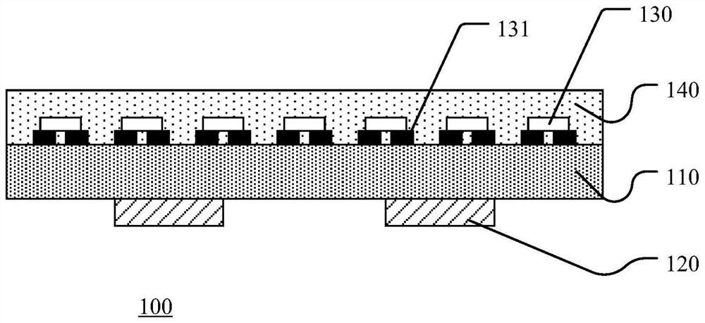
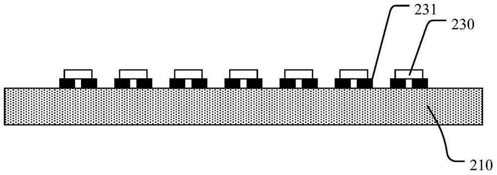
The invention discloses a manufacturing method of a LED display module. The method comprises the steps: fixing a plurality of LED chips to the first surface of a substrate, and electrically connecting the lower surface of each LED chip with the substrate; forming a packaging adhesive layer on the first surface of the substrate, wherein the packaging adhesive layer covers each LED chip and the exposed first surface of the substrate; flattening the packaging adhesive layer by adopting a grinding and polishing process until the upper surfaces of all the LED chips are exposed; and forming semi-transparent matte films on the upper surfaces of the packaging adhesive layer and the LED chips, wherein the packaging adhesive layer is a black colloid and is used for preventing optical crosstalk among the LED chips. According to the invention, the packaging adhesive layer above the surface of the LED chip is removed in a grinding and polishing mode so as to completely expose out the upper surface of the LED chip of the packaging adhesive layer and form the semitransparent matte film on the surface of the packaging adhesive layer, so that the light emitting effect of the LED chip is guaranteed, the thickness consistency of the LED display module is improved, and the phenomenon similar to mosaic generated among different lamp panels after a plurality of LED display modules are spliced is reduced.

Description

technical field [0001] The invention relates to the technical field of LED display screens, in particular to a method for manufacturing an LED display module. Background technique [0002] Recently, with the advancement of technology, the resolution of LED (Light-Emitting Diode) displays is getting higher and higher, the pixel pitch is getting smaller and the number of pixels is increasing. For LED displays with a pixel pitch of less than 0.8mm, because the LED chip pitch is too close to use front-mounted chips, only flip-chips can be used. At the same time, due to the close spacing between the LED chips of adjacent pixels, when the LED chips are lit, the light emitted by the adjacent LED chips will interfere with each other, and the cross-light phenomenon is more obvious, which makes the clarity of the LED display worse. , to reduce the display effect. [0003] In addition, in order to facilitate the assembly into larger-sized LED displays, the size of the LED display mod...

Claims


Application Information

Patent Timeline
IPC IPC(8): H01L25/16H01L33/48H01L33/56
CPCH01L25/167H01L33/48H01L33/56
Inventor 张汉春江忠永
Owner HANGZHOU MULTI COLOR OPTOELECTRONICS
Learn More