Fuel cell unit module and fuel cell

A fuel cell unit and unit module technology, which is applied in the direction of fuel cells, electrical components, circuits, etc., can solve the problems of large differences in reaction gas temperature, humidity, and concentration, battery performance degradation, and low local gas reaction efficiency.

Pending Publication Date: 2021-09-10
上海氢晨新能源科技有限公司
View PDF0 Cites 0 Cited by
  • Summary
  • Abstract
  • Description
  • Claims
  • Application Information

AI Technical Summary

Problems solved by technology

This traditional structure currently has the following problems: the cathode gas flow channel, the anode gas flow channel and the coolant flow channel do not have a unified and reasonable planning and layout, r

Method used


Image

  • Fuel cell unit module and fuel cell
  • Fuel cell unit module and fuel cell
  • Fuel cell unit module and fuel cell

Examples


Embodiment 1

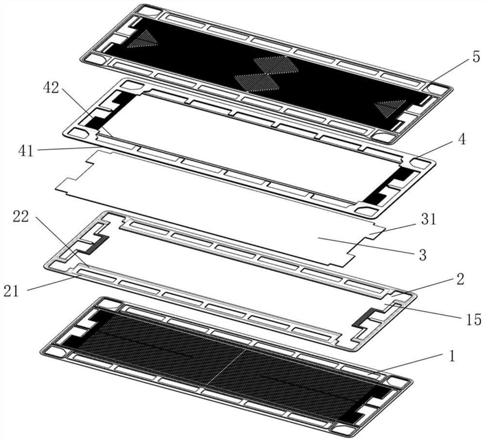
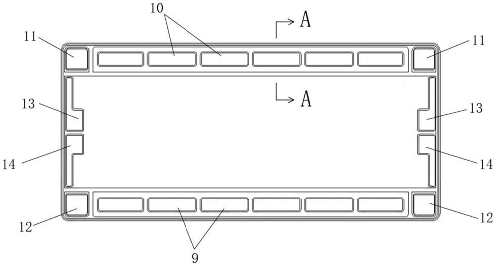
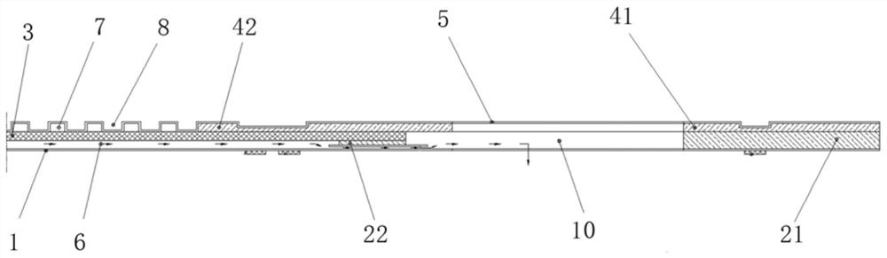
[0037] Such as Figure 1~3 As shown, this embodiment provides a fuel cell unit module, including a cathode plate 1 , a cathode injection molding seal 2 , a membrane electrode 3 , an anode injection molding seal 4 and an anode plate 5 which are sequentially stacked. The cathode injection molding seal 2 is an annular rectangular plate, including a first fitting edge 21 of the outer ring and a first clamping edge 22 of the inner ring. The anode injection molded seal 4 is also an annular rectangular plate, including a second fitting edge 41 of the outer ring and a second clamping edge 42 of the inner ring. The first fitting edge 21 and the second fitting edge 41 are attached to each other, and the surrounding sides of the membrane electrode 3 are clamped between the first clamping edge 22 and the second clamping edge 42 . The cathode plate 1 is attached to the lower layer of the cathode injection molding seal 2 , and the anode plate 5 is attached to the upper layer of the anode i...

Embodiment 2

[0045] This embodiment provides a fuel cell, including a stack core and an end plate. The electric stack core is formed by stacking fuel cell unit modules described in one embodiment of the life-death wheel, such as Figure 10 shown. This structure re-plans the smallest unit module of the core, and realizes the direct packaging of single-piece cathode plate, single-piece anode plate and membrane electrode through injection molding process. In the overall installation process of the fuel cell, only the unit modules need to be re-stacked to complete the assembly, which reduces the accuracy requirements of the traditional installation, and will not cause the bonding problem of the membrane electrode and the plate due to the installation, and improves the overall stability of the fuel cell sex.


PUM


Abstract

The invention relates to a fuel cell unit module and a fuel cell. The fuel cell unit module comprises a cathode plate, a cathode injection molding sealing element, a membrane electrode, an anode injection molding sealing element and an anode plate which are sequentially stacked; a cathode gas flow channel is arranged between the cathode plate and the membrane electrode; and an anode gas flow channel is arranged between the anode plate and the membrane electrode. When the plurality of unit modules are stacked, a coolant flow channel is formed between the cathode plate and the anode plate of two adjacent unit modules. The coolant flow channel and the anode gas flow channel are the same in layout, and a coolant in the coolant flow channel and anode gas in the anode gas flow channel are the same in flow direction; and the layout of the cathode gas flow channel and the anode gas flow channel is the same or locally the same, and the flow directions of cathode gas in the cathode gas flow channel and anode gas in the anode gas flow channel are opposite or locally opposite. Compared with the prior art, the Fuel cell unit module has the advantages of efficient internal gas reaction, capability of improving and overall battery performance, and the like.

Description

technical field [0001] The invention relates to the technical field of fuel cells, in particular to a fuel cell unit module and a fuel cell. Background technique [0002] Fuel cell is a kind of power generation device with the characteristics of environmental friendliness, high efficiency and long service life. Taking a hydrogen fuel cell (proton exchange membrane fuel cell) as an example, hydrogen gas enters the battery from the anode side of the battery, hydrogen atoms become protons after the anode loses electrons, and the protons pass through the proton exchange membrane inside the battery to reach the battery cathode, while the electrons The cathode of the battery is also reached via an external loop. On the cathode side of the battery, protons, electrons, and oxygen combine to form water, which generates an electric current. The traditional fuel cell core structure is a simple staggered stack of membrane electrodes and bipolar plates, with cathode gas flow channels a...

Claims


Application Information

Patent Timeline
IPC IPC(8): H01M8/0271H01M8/0258H01M8/0267
CPCH01M8/0271H01M8/0258H01M8/0267Y02E60/50
Inventor 翟桂珍程旌德徐一凡
Owner 上海氢晨新能源科技有限公司
Why Eureka
Try Eureka