Permanent magnet motor rotor, permanent magnet motor and processing method of permanent magnet motor rotor

A technique for permanent magnet motors and processing methods, which is applied in the manufacture of motor generators, magnetic circuit rotating parts, and stator/rotor bodies, etc., and can solve complex winding processes, long processing cycles, and low production efficiency of permanent magnet motors. question

Pending Publication Date: 2021-09-10
HENGDIAN GRP DMEGC MAGNETICS CO LTD
View PDF20 Cites 1 Cited by
  • Summary
  • Abstract
  • Description
  • Claims
  • Application Information

AI Technical Summary

Problems solved by technology

However, due to the complex winding process and long processing cycle, the overall production efficiency of permanent magnet motors is low and the production cost is high

Method used


Image

  • Permanent magnet motor rotor, permanent magnet motor and processing method of permanent magnet motor rotor
  • Permanent magnet motor rotor, permanent magnet motor and processing method of permanent magnet motor rotor
  • Permanent magnet motor rotor, permanent magnet motor and processing method of permanent magnet motor rotor

Examples


Embodiment 1

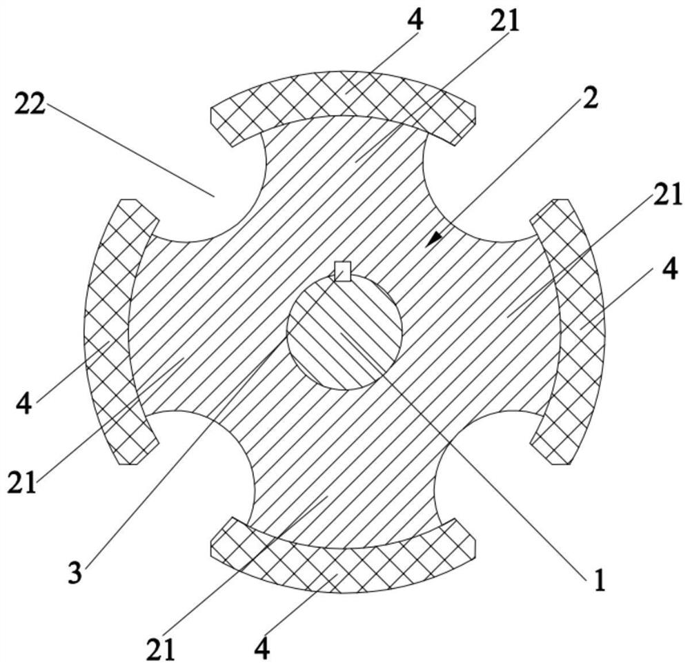
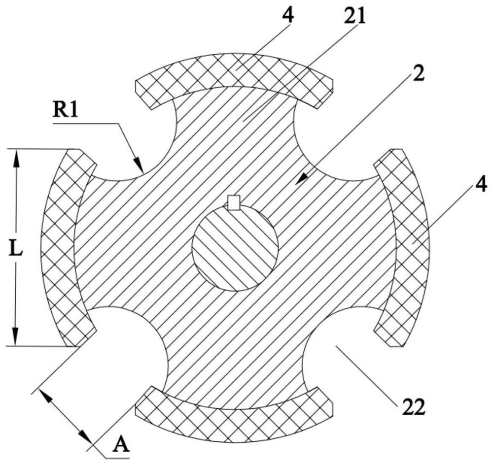
[0042] This embodiment provides a permanent magnet motor rotor, which includes a rotating shaft 1 , a silicon steel sheet group 2 and a plurality of magnetic tiles 4 .

[0043] Such as figure 1 As shown, the silicon steel sheet group 2 is sleeved on the rotating shaft 1 . Specifically, a shaft hole is provided at the center of the silicon steel sheet group 2, and the silicon steel sheet group 2 is sheathed on the rotating shaft 1 through the shaft hole. Further, key grooves are provided in the shaft hole and on the rotating shaft 1 respectively, and the fixing key 3 is installed in the key groove to realize the fixing between the silicon steel sheet group 2 and the rotating shaft 1 . The structure of the fixed key 3 is a prior art, and will not be repeated here.

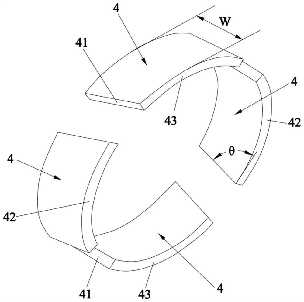
[0044] refer to figure 1 and image 3 A plurality of magnetic tiles 4 are fixed outside the silicon steel sheet group 2 at intervals along the circumferential direction of the silicon steel sheet group 2 (that is...

Embodiment 2

[0070] The present embodiment provides a kind of processing method of permanent magnet motor rotor, and it comprises the following steps:

[0071] (1) Set the silicon steel sheet group 2 on the rotating shaft 1 , and realize the fixing between the silicon steel sheet group 2 and the rotating shaft 1 through the fixing key 3 .

[0072] (2) A plurality of magnetic tiles 4 corresponding to the number of poles of the permanent magnet motor are subjected to chamfering processing. During chamfering, the two ends of each magnetic tile 4 in the circumferential direction are respectively inclined relative to the axial direction of the magnetic tile 4 and the direction of inclination is opposite. , to form the chamfered surface 41 .

[0073] In fact, the processing process of the traditional magnetic tile is as follows: firstly, the width, length and bow height of the blank of the magnetic tile are ground, then automatic internal and external chamfering, rough and fine grinding of the i...


PUM


Abstract

The invention discloses a permanent magnet motor rotor, a permanent magnet motor and a processing method of the permanent magnet motor rotor, which relate to the technical field of motors. The permanent magnet motor rotor comprises a rotating shaft, a silicon steel sheet group and a plurality of magnetic shoes. The silicon steel sheet group sleeves the rotating shaft, the plurality of magnetic shoes are fixed outside the silicon steel sheet group at intervals along the circumferential direction of the silicon steel sheet group, two ends of each magnetic shoe in the circumferential direction are respectively and reversely arranged in an inclined manner relative to the axis of the magnetic shoe to form two diagonal planes, and the opposite diagonal planes of two adjacent magnetic shoes are arranged in parallel. Energy loss can be effectively reduced during operation of the permanent magnet motor, the overall production efficiency of the permanent magnet motor can be improved, and the production cost is reduced.

Description

technical field [0001] The invention relates to the technical field of motors, in particular to a permanent magnet motor rotor, a permanent magnet motor and a processing method for the permanent magnet motor rotor. Background technique [0002] Permanent magnet motors are more and more used in new energy electric vehicles because of their advantages such as less heat generation, simple structure, small size, light weight and low noise. New energy electric vehicles require permanent magnet motors to operate with as little energy loss as possible, so as to have strong torque at low speeds to ensure starting torque, while supporting higher cruising range. [0003] Traditional permanent magnet motors often use positive-shaped magnetic tiles (the length and width of the magnetic tiles are vertically arranged, and the expanded shape of the magnetic tiles is rectangular), so a zigzag magnetic field distribution will be formed during operation, and the energy loss will be large. In...

Claims


Application Information

Patent Timeline
Patent Type & Authority Applications(China)
IPC IPC(8): H02K1/27H02K1/28H02K15/03
CPCH02K1/2753H02K1/28H02K15/03H02K2213/03Y02T10/64H02K1/278H02K2201/06
Inventor 翁凤华吴翔亮翁乐洋
Owner HENGDIAN GRP DMEGC MAGNETICS CO LTD
Why Eureka
Try Eureka