Motor rotor assembling workbench

A technology of motor rotor and workbench, which is applied in the manufacture of stator/rotor body, etc., which can solve the problems of unsatisfactory installation accuracy, increased labor intensity of workers, and reduced production quality.

Active Publication Date: 2021-09-10
SHENZHEN GOLF & FEIHUANG TECH
View PDF5 Cites 2 Cited by
  • Summary
  • Abstract
  • Description
  • Claims
  • Application Information

AI Technical Summary

Problems solved by technology

[0003] At present, the existing motor rotors usually encounter the following problems in the assembly process: a. The motor rotor and the housing are assembled manually, and the alignment process of the motor rotor and the housing can only be completed by manual visual inspection during assembly , due to the high installation accuracy requirements of the motor rotor and housing, manual installation will not only increase the difficulty of the installation process, but also fail to meet the installation accuracy requirements, thereby reducing the production quality; b. After the assembly is completed, manual installation is required Manual unloading will not only increase the labor intensity of workers and consume a lot of time, but also reduce the assembly efficiency of the next set of motor rotors and housings

Method used


Image

  • Motor rotor assembling workbench
  • Motor rotor assembling workbench
  • Motor rotor assembling workbench

Examples


Embodiment Construction

[0023] Embodiments of the present invention will be described below with reference to the drawings. In the process, in order to ensure the clarity and convenience of illustration, we may exaggerate the width of the lines or the size of the constituent elements in the diagram.

[0024] In addition, the following terms are defined based on the functions in the present invention, and may be different according to user's intention or practice. Therefore, these terms are defined based on the entire content of this specification.

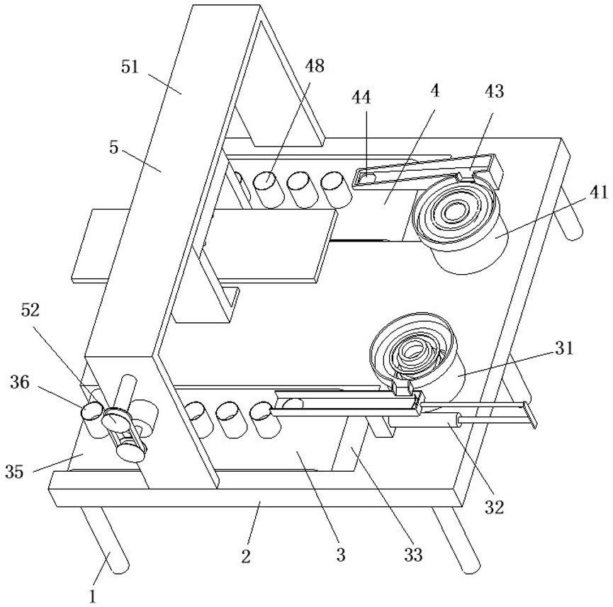
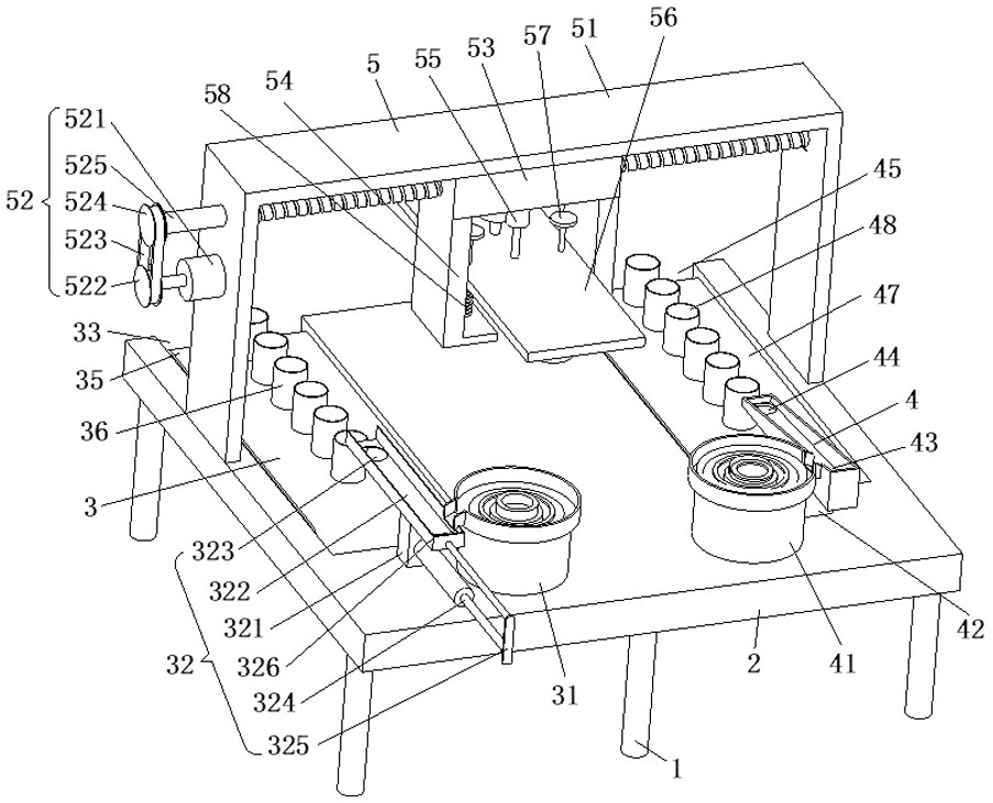
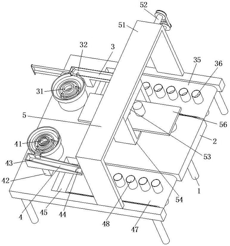
[0025] refer to Figure 1 to Figure 3 , a motor rotor assembly workbench, including a leg 1, a support plate 2, a housing feeding device 3, a rotor feeding device 4 and a press-fitting device 5, the legs 1 are provided with a plurality, and the plurality of The support plate 2 is fixedly connected to the upper ends of the legs 1 described above, the shell feeding device 3 is installed on the support plate 2 near the front side, and the rotor feeding dev...


PUM


Abstract

The invention relates to the field of motor rotor assembling, in particular to a motor rotor assembling workbench which comprises supporting legs, a supporting plate, a shell feeding device, a rotor feeding device and a press fitting device. The motor rotor assembling workbench can solve the following problems that in the assembling process of an existing motor rotor, a, the motor rotor and a shell are assembled manually, the alignment process of the motor rotor and the shell can be completed only through manual visual inspection during assembling, and due to the fact that the requirement for the mounting precision of the motor rotor and the shell is high, by adopting a manual mounting mode, the difficulty degree of the mounting process is increased, the requirement of mounting precision cannot be met, and thus the production quality is reduced; and b, after the assembling is finished, manual blanking is needed, so that the labor intensity of workers is increased, a large amount of time is consumed, and meanwhile, the next assembling efficiency of the motor rotor and the shell is also reduced.

Description

technical field [0001] The invention relates to the field of motor rotor assembly, in particular to a motor rotor assembly workbench. Background technique [0002] The motor rotor of the coreless motor usually includes two parts: the motor rotor body and the housing. The housing can play a good role in protecting the motor rotor body; during the manufacturing process of the coreless motor, the motor rotor needs to be assembled into the housing. [0003] At present, the existing motor rotors usually encounter the following problems in the assembly process: a. The motor rotor and the housing are assembled manually, and the alignment process of the motor rotor and the housing can only be completed by manual visual inspection during assembly , due to the high installation accuracy requirements of the motor rotor and housing, manual installation will not only increase the difficulty of the installation process, but also fail to meet the installation accuracy requirements, thereby...

Claims


Application Information

Patent Timeline
Patent Type & Authority Applications(China)
IPC IPC(8): H02K15/02
CPCH02K15/02
Inventor 杨贺敏
Owner SHENZHEN GOLF & FEIHUANG TECH
Why Eureka
Try Eureka