Microwave generator and anti-eavesdropping device thereof

A microwave generator and anti-eavesdropping technology, applied in the microwave field, can solve the problem of single anti-eavesdropping means

Pending Publication Date: 2021-09-10
陕西中控微脉智能科技有限公司
View PDF4 Cites 0 Cited by
  • Summary
  • Abstract
  • Description
  • Claims
  • Application Information

AI Technical Summary

Problems solved by technology

[0005] Facing the above-mentioned technical background, the present invention is aimed at the single problem of anti-eavesdropping means, and proposes a microwave generator and its anti-eavesdropping device to make up for the deficiencies in anti-eavesdropping technology and enrich

Method used


Image

  • Microwave generator and anti-eavesdropping device thereof
  • Microwave generator and anti-eavesdropping device thereof
  • Microwave generator and anti-eavesdropping device thereof

Examples


Embodiment 1

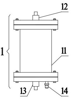
[0035] Such as figure 1 As shown, the microwave generator 1 includes a housing 11, a high-pressure end 12, a low-pressure end 13, and an inflatable end 14. The high-pressure end 12 and the low-pressure end 13 are respectively arranged at both ends of the housing 11. The inflatable end 14 is a one-way valve and Used to fill the housing 11 with insulating gas. In the figure, the housing 11 has flange structures, and sealing gaskets are arranged between the flange structures. Specifically, the housing 11 is hollow to form a microwave cavity 111 , a cover 112 is installed at the openings at both ends of the microwave cavity 111 , and a seal 113 is provided between the contact surface of the cover 112 and the opening.

[0036] It should be noted that the housing 11 of the microwave generator 1 is made of non-metallic material to ensure normal microwave radiation, and the covers 112 at both ends are made of metal material to form a resonant cavity.

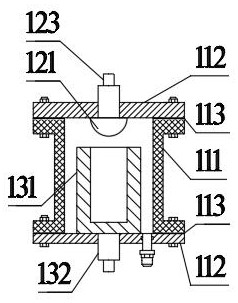
[0037] figure 2 Among them, ...

Embodiment 2

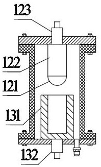
[0042] Such as image 3 As shown, the high voltage end 12 also includes a discharge body 122 for installing a discharge head 121 . In the figure, the discharge body 122 is a metal cylinder, and a discharge head 121 is installed at the end of the discharge body 122, and the discharge head 121 and the discharge cylinder 131 are arranged in a non-contact manner.

Embodiment 3

[0044] Such as Figure 4 As shown, the high voltage end 12 also includes a discharge body 122 for installing a discharge head 121 . In the figure, the discharge body 122 is a metal truncated cone, and a discharge head 121 is installed at the end of the discharge body 122, and the discharge head 121 and the discharge cylinder 131 are arranged in a non-contact manner.

[0045] It should be noted that the discharge body 122 is one of metal cylinders or metal cones, and the discharge head 121 can be one of metal spheres, metal hemispheres, metal ellipsoids, metal semi-ellipsoids or other arc shapes. . According to different application occasions and actual requirements, it is generally expressed as a requirement for the waveform of the radiated microwave and the size of the radiated energy. Sometimes the cylinder is removed, and only the hemisphere or the entire sphere is retained. The common structure is as follows: figure 2 and image 3 as well as Figure 4 shown.


PUM


Abstract

The invention provides a microwave generator and an anti-eavesdropping device thereof, and belongs to the technical field of microwaves, the microwave generator comprises a shell, a high-voltage end, a low-voltage end, an inflation end and the like, the microwave generator adopts a novel structure and a novel microwave generation mode, and the microwave generator is a microwave device which is simple in structure and integrates multiple functions of loop conduction and microwave radiation. The anti-eavesdropping device designed based on the microwave generator, the pulse high-voltage modulator, the radiating antenna and the like has dual functions of long-distance interference and short-distance attack, the eavesdropping device can lose functions or be directly damaged, the non-contact active anti-eavesdropping function is achieved, the actual application requirements of different occasions are met. The design makes up the blank in the current domestic anti-eavesdropping related field, and can be widely applied to the field of electronic equipment countering.

Description

technical field [0001] The invention relates to a microwave generator and an anti-tapping device thereof, belonging to the field of microwave technology, in particular to a portable non-contact active anti-tapping device. Background technique [0002] In the information age, with the rapid development of communication technology, mobile communication equipment has become an indispensable tool in people's daily life. While mobile communication equipment brings convenience to human beings, it also creates some problems that cannot be ignored. For example, criminals use professional mobile communication equipment, such as monitors, bugs, etc., to realize remote eavesdropping by covertly recording sounds. Stealing commercial secrets, technical secrets, political secrets, and matters related to major national policies, etc., seriously damages the interests of others, collective interests and even national interests. In order to solve this problem, anti-eavesdropping technology a...

Claims


Application Information

Patent Timeline
IPC IPC(8): H04K3/00
CPCH04K3/62H04K3/82
Inventor 陈炎伟李伟李立明
Owner 陕西中控微脉智能科技有限公司
Why Eureka
Try Eureka