
Combustion flue gas desulfurization and denitrification tower

A technology for desulfurization, denitrification, and combustion of flue gas. It is applied in gas treatment, filtration circuits, and dispersed particle filtration. It can solve the problems of wasting reaction solution, troublesome cleaning or maintenance, and affecting the effect of flue gas purification.

Pending Publication Date: 2021-09-14
郭建成
View PDF11 Cites 1 Cited by
  • Summary
  • Abstract
  • Description
  • Claims
  • Application Information

AI Technical Summary

Problems solved by technology

[0003] The common wet desulfurization and denitrification tower intake switch and spray switch are controlled separately. If the intake switch is activated first, the flue gas will enter the reaction chamber first, and the flue gas that first enters the reaction chamber will not react completely with the reaction liquid, affecting the flue gas. the purification effect; priority activation of the spray switch will cause the reaction solution to be sprayed first, although it will not affect the purification effect of the flue gas, but will cause waste of the reaction solution; ordinary sulfur denitrification dust collectors are all operations that spray first and then remove dust During the reaction process between flue gas that has not been dedusted and the reaction solution, the dust particles in the flue gas contact with the reaction solution, which not only affects the purification effect of the flue gas, but also wastes the reaction solution. After the dust particles in the flue gas contact with the reaction solution Increase the volume of dust particles, so the dust particles in the flue gas often block the holes, which is troublesome to clean or maintain, and also increases the cost; during the evolution process of the flue gas and the reaction solution, there is a reaction between the reaction solution and the flue gas Incomplete, the reaction solution remains at the bottom of the reaction chamber and is discharged out of the desulfurization tower along the liquid outlet, resulting in a waste of the cost of the reaction solution

Method used


Image

  • Combustion flue gas desulfurization and denitrification tower
  • Combustion flue gas desulfurization and denitrification tower
  • Combustion flue gas desulfurization and denitrification tower

Examples


Embodiment approach

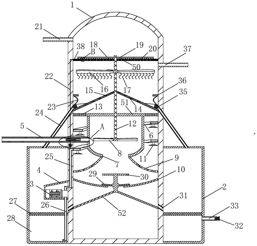
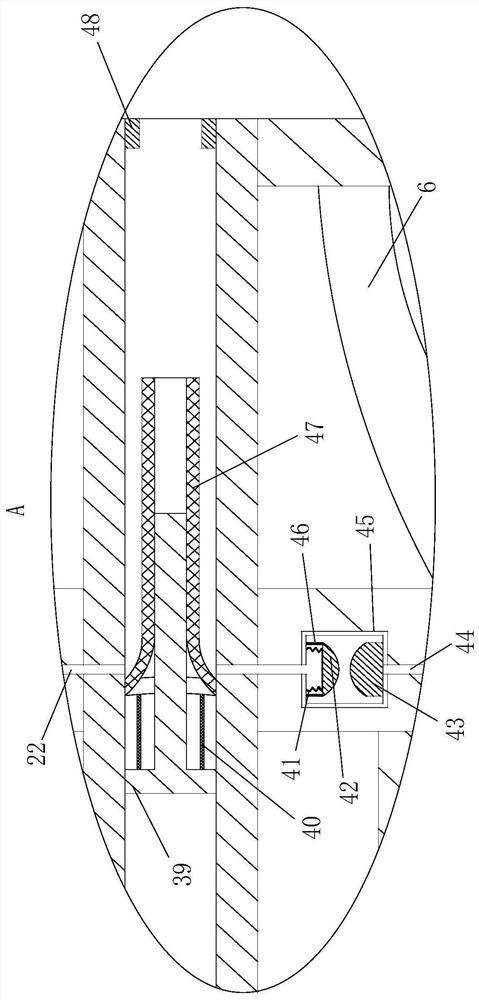
[0027] As an embodiment of the present invention, an arc-shaped plate 10 is fixedly connected to the side wall of the tower body 1; the arc-shaped plate 10 is located below the first filter plate 9; the side wall of the tower body 1 is fixedly connected There is a spiral tube 6; the spiral tube 6 is located above the first filter plate 9 and surrounds the outer surface of the dust removal chamber 7; the surface of the spiral tube 6 is fixedly connected with uniformly arranged spray heads 11; the spray The head 11 is connected to the inner space design of the spiral pipe 6; the left side wall of the tower body 1 is fixedly connected with a water outlet pipe 25; the top of the water outlet pipe 25 is connected to the inner space design of the spiral pipe 6; the interior of the collection cavity 2 A trapezoidal groove 4 is opened; a water pump 3 is fixedly connected inside the trapezoidal groove 4; the bottom of the water outlet pipe 25 is fixedly connected with the water pump 3; ...


PUM


Abstract

The invention belongs to the technical field of combustion flue gas purification, and particularly relates to a combustion flue gas desulfurization and denitrification tower which comprises a tower body, a dust removal unit and a desulfurization unit, wherein a collecting cavity is fixedly connected to the peripheral side of the bottom of the tower body; a first partition plate is fixedly connected to the middle of the inner wall of the tower body; a dust removal cavity is fixedly connected below the first partition plate; first air outlet holes are uniformly formed in the surface of the first partition plate; the first air outlet holes are formed in the peripheral side of the top of the dust removal cavity; the middle of the first partition plate is rotationally connected with a rotating rod in a sealed mode; a first filter plate is fixedly connected to the bottom of the dust removal cavity, and drifting flue gas penetrates through the first filter plate in the process of flowing towards the outer side of the dust removal cavity, so that dust particles in the flue gas are filtered in a lower surface space of the first filter plate, the dust particles in the flue gas can be effectively filtered out, and the phenomenon that holes are blocked by the dust particles in the flue gas is effectively reduced; and the recycling of the reaction solution can effectively save the cost, and synchronously improve the flue gas desulfurization and denitrification effects.

Description

technical field [0001] The invention belongs to the technical field of combustion flue gas purification, in particular to a combustion flue gas desulfurization and denitrification tower. Background technique [0002] Flue gas desulfurization and denitrification means that the flue gas enters the desulfurization tower and contacts the reaction solution inside the tower body, and the acidic oxide sulfur dioxide and other pollutants in the flue gas are absorbed by the reaction solution, and then the flue gas is subjected to dust removal treatment. It can be fully purified, and finally the comprehensive treatment of flue gas desulfurization and denitrification can be realized. [0003] The common wet desulfurization and denitrification tower inlet switch and spray switch are separate controls. Activating the inlet switch first will cause the flue gas to enter the reaction chamber first, and the flue gas that first enters the reaction chamber will not react completely with the re...

Claims


Application Information

Patent Timeline
IPC IPC(8): B01D53/60B01D53/78B01D53/79B01D53/96B01D46/12B01D36/00
CPCB01D53/60B01D53/78B01D53/79B01D53/96B01D46/12B01D36/001B01D2258/0283
Inventor 郭建成赵涛
Owner 郭建成
Learn More