Stamping and bending device for steel products

A technology for stamping, bending and steel products, which is applied in the direction of feeding device, positioning device, storage device, etc., which can solve the problems of inconvenient promotion and implementation, inaccurate stamping and bending, and unstable positioning of the stamping device.

Pending Publication Date: 2021-09-14
长兴锐锋机械有限公司
View PDF1 Cites 0 Cited by
  • Summary
  • Abstract
  • Description
  • Claims
  • Application Information

AI Technical Summary

Problems solved by technology

The positioning of the stamping device is unstable, resulting in inaccurate stamping and bending, which is not convenient for popularization and implementation

Method used


Image

  • Stamping and bending device for steel products
  • Stamping and bending device for steel products
  • Stamping and bending device for steel products

Examples


Embodiment 1

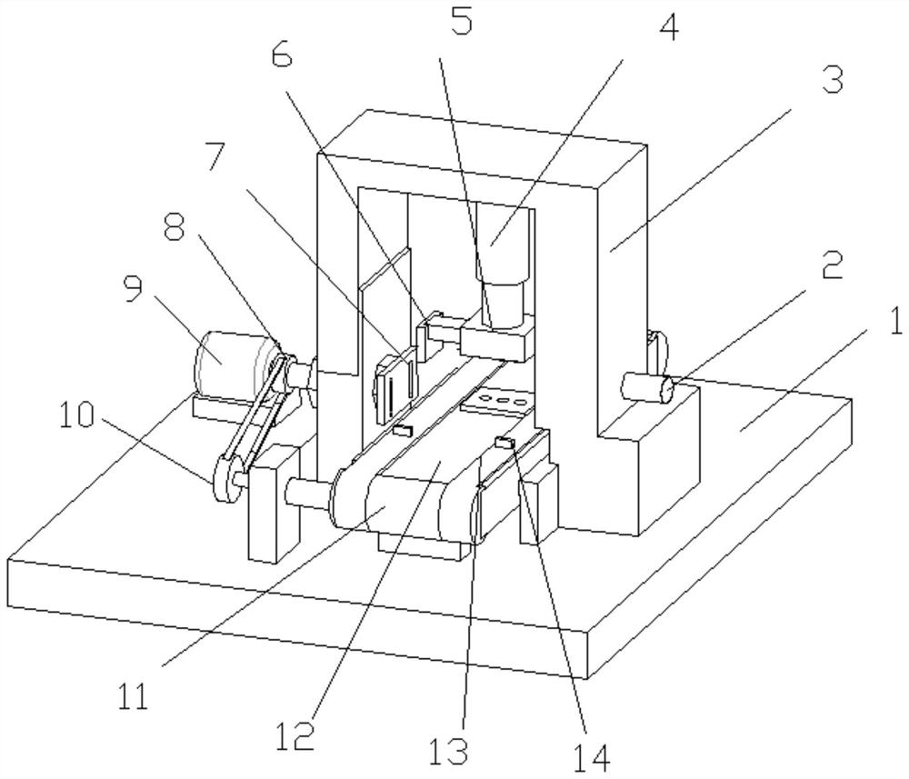
[0026] see Figure 1-3 , a stamping and bending device for steel products, including a bottom plate 1, a workbench 12 and stamping parts 5. A mounting frame 3 is fixedly arranged on the upper surface of the bottom plate 1, and the mounting frame 3 is an inverted U-shaped structure. The inner top of the installation frame 3 is fixedly connected to the top of the hydraulic rod 4, the bottom of the hydraulic rod 4 is fixedly connected to the stamping part 5, and the end of the stamping part 5 is fixedly connected to the bent pressing part 6. Under the action of the hydraulic rod 4, the hydraulic pressure The rod 4 is elongated, so that the punching part 5 and the bending part 6 are lowered, thereby completing the punching and bending. The inner side wall of the mounting bracket 3 is provided with a vertical sliding groove 25, and the end of the stamping part 5 is fixedly connected with a sliding rod 23, and the end of the sliding rod 23 is slidably nested in the inside of the sl...

Embodiment 2

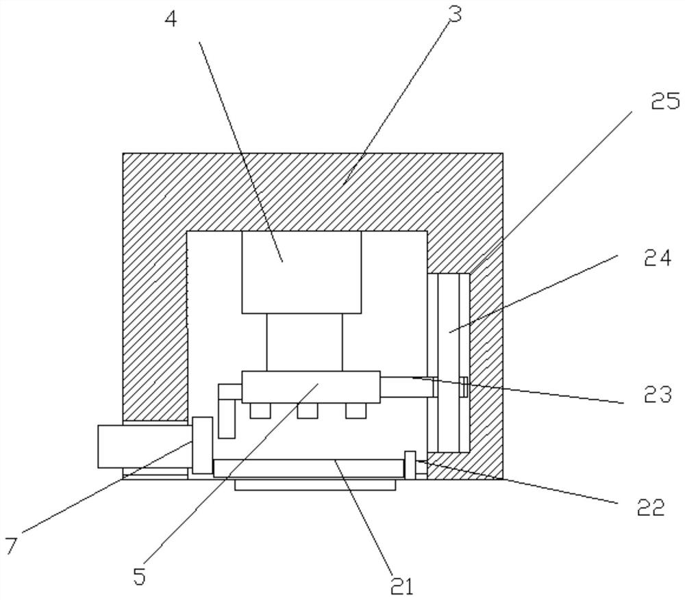
[0031] see Figure 4 , on the basis of Embodiment 1, the opposite side of the positioning plate 7 is provided with a positioning top plate 22 on the inner wall of the mounting frame 3, and under the action of the positioning plate 7 and the positioning top plate 22, the positioning top plate 22 and the positioning plate 7 stand on the steel product 21, so that the location of the steel product 21 is accurate, and it is convenient to improve the stamping of the steel product 21 more accurately. The positioning top plate 22 is connected with an adjustment member 2, and the position of the positioning top plate 22 can be adjusted through the adjustment member 2, thereby adjusting the bending position and improving the applicability of the device. The adjusting part 2 includes a screw mandrel 26 and a rotating sleeve 27. The positioning top plate 22 is fixedly connected to the end of the screw mandrel 26. The screw mandrel 26 slides and nests inside the screw mandrel 26. The screw...


PUM


Abstract

The invention relates to the technical field of steel material processing, and particularly discloses a stamping and bending device for steel products. The stamping and bending device comprises a bottom plate, a workbench and a stamping part; a mounting frame is fixedly arranged on the upper surface of the bottom plate; the inner top of the mounting frame is fixedly connected to the top of a hydraulic rod; the bottom of the hydraulic rod is fixedly connected with the stamping part and a bending pressing part; a motor is fixedly mounted on the side edge of the mounting frame and is located on the upper surface of the bottom plate; an output shaft of the motor is coaxially and fixedly connected with a driving belt wheel and a rotating shaft; a moving sleeve is rotationally nested on the rotating shaft; a first ball is rotationally arranged in the moving sleeve; the moving sleeve slidably penetrates through a cavity in the side wall of the mounting frame; a positioning plate is arranged on the end part of the moving sleeve; the workbench is arranged on the bottom plate below the stamping part; rotating rollers are rotationally arranged at two ends of the workbench; and the rotating roller at one end is coaxially and fixedly connected with a driven belt wheel. The device has the advantages of being simple in structure, convenient to operate, accurate in positioning, good in safety, low in production cost and convenient to popularize and implement.

Description

technical field [0001] The invention relates to the technical field of rigid material processing, in particular to a stamping and bending device for steel products. Background technique [0002] Stamping and bending are the forming and processing methods of applying external force to plates, strips, pipes and profiles to cause plastic deformation or separation, so as to obtain workpieces (stamping parts) of required shape and size. At present, 60-70% of the steel products in the world are plates, most of which are stamped into finished products, especially in the automobile manufacturing industry, the car body, chassis, fuel tank, and radiator fins all need to be stamped. To ensure the stamping effect, it is necessary to carry out continuous stamping on the plate, and ensure that the pressure of each stamping is the same. [0003] Chinese patent (notification number: CN 207494284 U, announcement date: 2018.06.15) discloses a continuous stamping device for steel products, in...

Claims


Application Information

Patent Timeline
IPC IPC(8): B21D35/00B21D43/00B21D43/12
CPCB21D35/003B21D43/003B21D43/12
Inventor 许华
Owner 长兴锐锋机械有限公司
Why Eureka
Try Eureka