Method for implementing machining through lasers, device of method and machine tool

A machining and laser technology, applied in the field of machining, can solve the problems of limited laser application range, decreased machining accuracy, and inability to implement long-axis parts machining.

Pending Publication Date: 2021-09-14
SHANGHAI NAGOYA PRECISION TOOLS
View PDF0 Cites 0 Cited by
  • Summary
  • Abstract
  • Description
  • Claims
  • Application Information

AI Technical Summary

Problems solved by technology

However, as the aspect ratio of the processed parts increases (that is, the length of the workpiece is greater than 300mm), the processing accuracy of th

Method used


Image

  • Method for implementing machining through lasers, device of method and machine tool
  • Method for implementing machining through lasers, device of method and machine tool

Examples


Embodiment Construction

[0046] The technical solution of the present invention will be described in detail below in conjunction with the accompanying drawings. The embodiments of the present invention are only used to illustrate the technical solutions of the present invention without limitation. Although the present invention has been described in detail with reference to the preferred embodiments, those skilled in the art should understand that the technical solutions of the invention can be modified or equivalently replaced , without departing from the spirit and scope of the technical solution of the present invention, all of which shall be covered by the claims of the present invention.

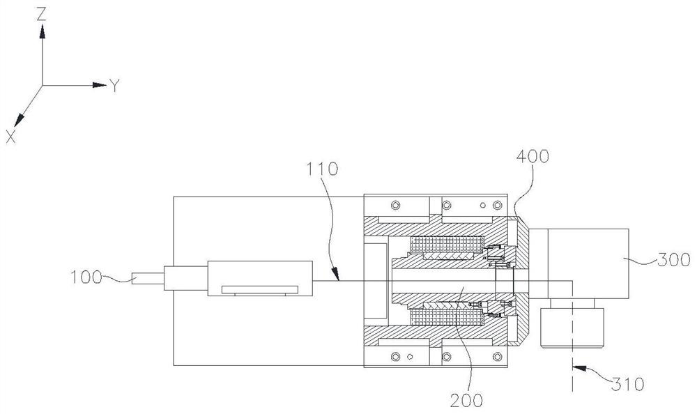
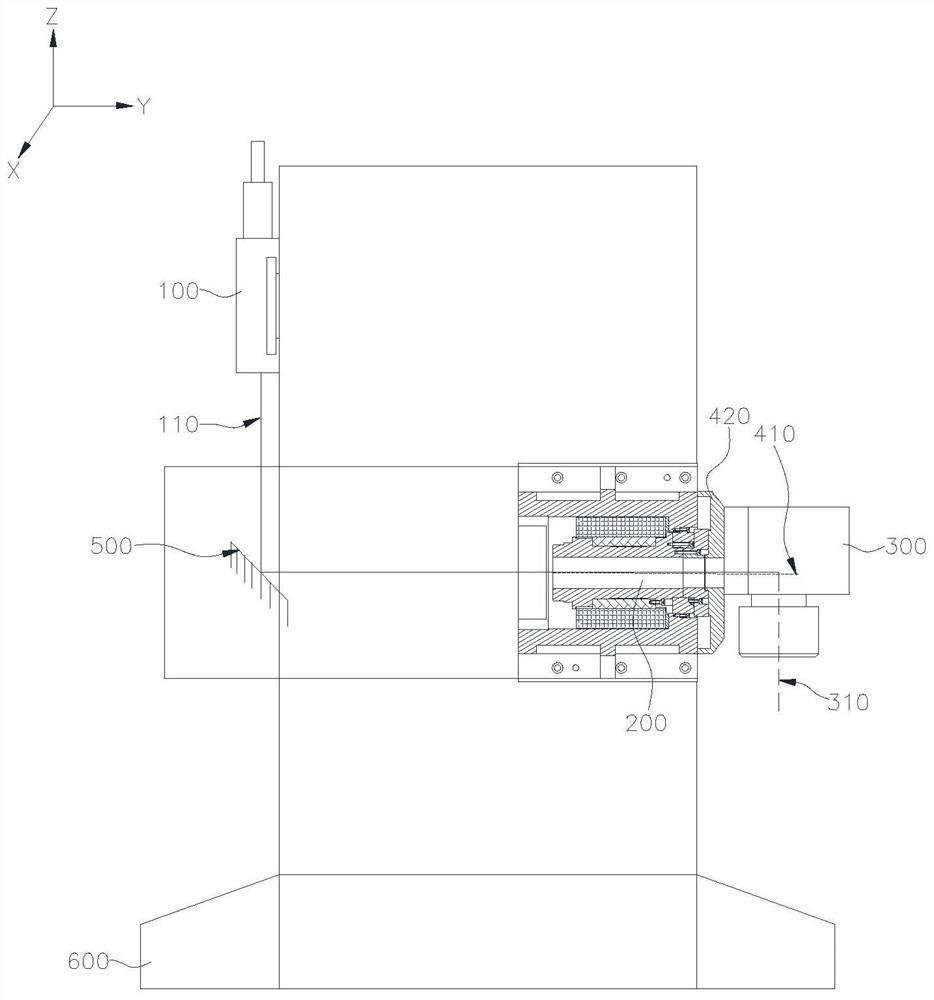
[0047] In the laser machining method provided in this embodiment, the laser light emitted by the laser emitter is first injected into a section of the cavity, and then emitted from the cavity, received by the light emitting component, and finally emitted by the light emitting component for processing the workpie...


PUM


Abstract

The invention providers a method for implementing machining through lasers. Lasers emitted by a laser emitter firstly enter a section of cavity channel, then the lasers are received by a light emitting component after being emitted out of the cavity channel, and finally the lasers are emitted out of the light emitting component to be used for implementing machining on a workpiece; and the lasers propagate along a straight line, and the intersection angle between the propagation path and a rotating axis is 0-15 degrees. A device manufactured through the method for implementing machining through lasers is installed on a multi-axis machine tool and combined with three linear motion axes and a rotary motion axis used for fixing the workpiece to form a space multi-axis laser machining scheme, the workpiece is machined through lasers in a rotary manner, the positioning error of lasers in machining is reduced, and the precision of laser machining is improved.

Description

technical field [0001] The invention relates to a machining method, in particular to a method for implementing precision machining on hard materials by using laser as the main means, and realizing industrialized precision machining of blades. Background technique [0002] The laser is a high-precision instrument, and the generator is connected to the laser head through a hard optical path or an optical fiber. The hard optical path usually cannot be moved frequently, and the optical fiber can only move gently in a small range of space, which cannot meet the efficiency and accuracy requirements of multi-axis (such as: three-axis, four-axis, five-axis and six-axis, etc.) precision machining . [0003] In order to improve the machining efficiency of laser, a swing head structure is applied to multi-axis machining, which is suitable for XA+YZB multi-axis laser machining. It directly connects the cutting structure and the laser output end, the laser output end swings with the ro...

Claims


Application Information

Patent Timeline
IPC IPC(8): B23K26/38B23K26/064B23K26/06B23K26/70
CPCB23K26/38B23K26/064B23K26/0643B23K26/702
Inventor 孙思叡
Owner SHANGHAI NAGOYA PRECISION TOOLS
Why Eureka
Try Eureka