Thermal print head and method of making the same

A technology of a thermal print head and a manufacturing method, which is applied in the printing field, can solve problems such as low thermal conductivity, reduce the heat conduction efficiency of a heating element to a printing medium, and improve durability and reliability, increase heat conduction efficiency, and practicability strong effect

Active Publication Date: 2022-07-01
POSTEK ELECTRONICS
View PDF8 Cites 0 Cited by
  • Summary
  • Abstract
  • Description
  • Claims
  • Application Information

AI Technical Summary

Problems solved by technology

In an embodiment of the thin-film thermal print head 100, the individual electrodes 22 and the common electrodes 21 are made of Al, and both have a thickness of 1-3 μm. The electrode layer steps, therefore, use SiO 2 or Si 3 N 4 The thickness of the protective layer needs to be greater than the thickness of the individual electrodes 22 and the common electrode 21, reaching 3-8 μm; in the thick film type thermal print head 200, the common electrode 2 and the individual electrodes 22 are made of Au, and the thickness is 0.6μm, there are also 0.6μm electrode layer steps at both ends of the resistance heating part 31, therefore, the thickness of the protective layer formed by screen printing glass glaze needs to be designed to be 4-8μm, or the protective layer formed by sputtering SiAlON The thickness of the layer is 2-4μm, which is far more than the height of the electrode layer; due to the SiO 2 、Si 3 N 4 , glass glaze, SiAlON and other insulating protective layers are all low thermal conductivity materials, and the increase in their thickness will further reduce the heat transfer efficiency of the heat transfer from the heating element to the printing medium

Method used


Image

  • Thermal print head and method of making the same
  • Thermal print head and method of making the same
  • Thermal print head and method of making the same

Examples


no. 1 example

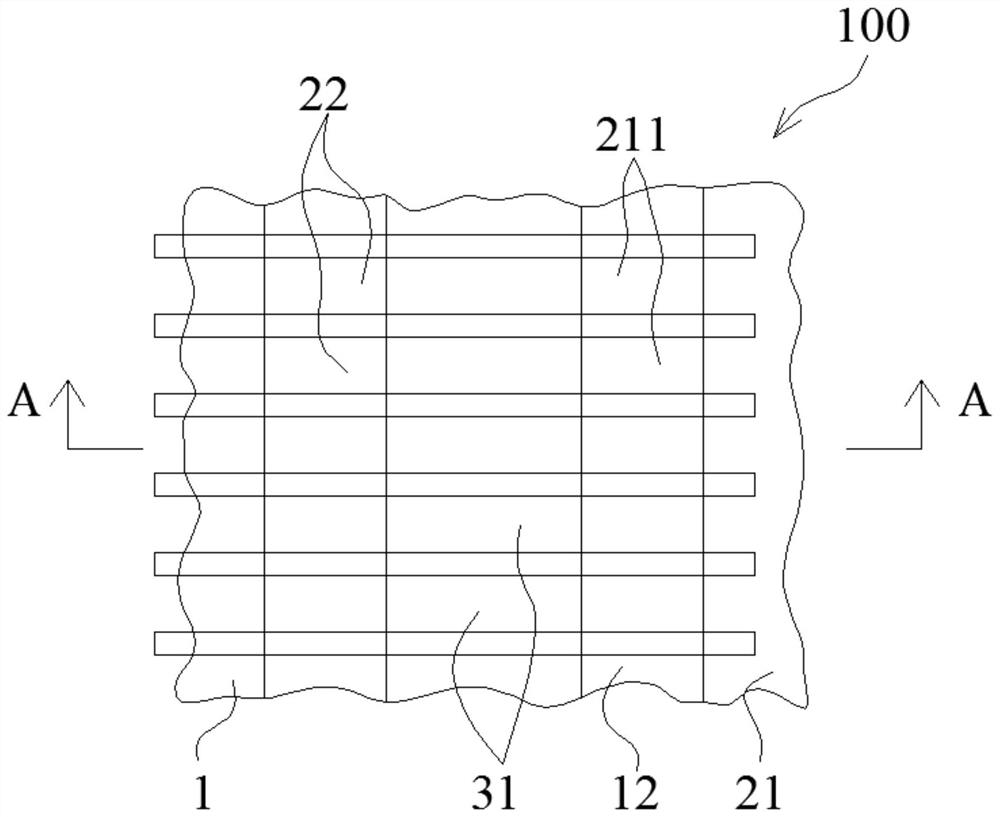
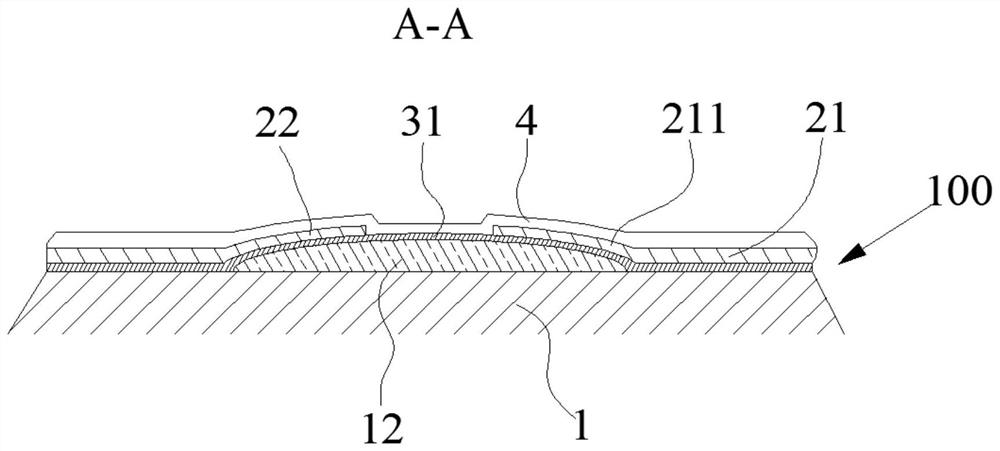
[0059] Figure 5 A schematic structural diagram of the thermal print head according to the first embodiment of the present invention is shown; Image 6 show Figure 5 The thermal printhead shown is a cross-sectional view along C-C. Specifically, the thermal print head 300 includes an insulating substrate 1 , an electrode layer 2 , a resistance layer 3 , and a protective layer 4 . The thermal print head 300 is assembled in a thermal transfer apparatus (not shown in the figure) for printing thermal photos, images, and the like.

[0060] In this embodiment, the insulating substrate 1 is made of alumina ceramics. The thermal print head 300 further includes a heat storage layer 12 formed on the top surface of the insulating substrate 1 . The heat storage layer 12 can be a glass glaze made of screen-printed amorphous glass paste and sintered, such as Image 6 shown.

[0061] The top surface of the heat storage layer 12 is provided with a first groove 121 and a second groove 12...

no. 2 example

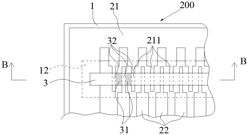
[0087] like Figure 13 and Figure 14 shown, Figure 13 A schematic structural diagram of the thermal print head according to the second embodiment of the present invention is shown; Figure 14 show Figure 13 A cross-sectional view of the thermal print head in the direction of D-D; specifically, the thermal print head 300 includes an insulating substrate 1 , an electrode layer 2 , a resistance layer 3 , and a protective layer 4 . The thermal print head 300 is assembled in a thermal transfer apparatus, and prints thermal photos, images, and the like.

[0088] In this embodiment, the insulating substrate 1 is formed of alumina ceramics. The thermal print head 300 further includes a heat storage layer 12 formed on the top surface of the insulating substrate 1 . The heat storage layer 12 can be a glass glaze made of screen-printed amorphous glass paste and sintered, such as Figure 14 shown.

[0089] The top surface of the heat storage layer 12 is provided with a first gro...


PUM

PropertyMeasurementUnit
thicknessaaaaaaaaaa
thicknessaaaaaaaaaa
depthaaaaaaaaaa

Abstract

The present invention provides a thermal print head and a manufacturing method thereof. The thermal print head includes an insulating substrate (1), an electrode layer (2), and a resistance layer (3); the thermal print head (300) further includes a heat storage layer (12) formed on the top surface of the insulating substrate (1); The top surface of the heat storage layer (12) is provided with a first groove (121) and a second groove (122) which are arranged independently at intervals from each other; the electrode layer (2) includes a first electrode and a second electrode; the first electrode accommodates In the first groove (121), the second electrode is accommodated in the second groove (122); the height of the top surface of the first electrode and the height of the top surface of the second electrode are respectively flush with the height of the top surface of the heat storage layer (12). ; The resistance layer (3) respectively covers the top surface of the heat storage layer (12), the top surface of the first electrode and the top surface of the second electrode. The thermal print head and the manufacturing method thereof in this embodiment are novel in design and strong in practicability.

Description

technical field [0001] The invention relates to the technical field of printing, in particular to a thermal printing head and a manufacturing method thereof. Background technique [0002] The thermal print head includes components such as a heat sink, a ceramic substrate, a PCB printed circuit board, and a driver IC. A glass glaze layer is prepared on the ceramic substrate as a heat storage layer, and the upper part of the heat storage layer is respectively covered with a resistance layer, an electrode layer and a protective layer. As a well-known thermal print head, it is generally classified into a thin film type thermal print head and a thick film type thermal print head. [0003] figure 1 A schematic diagram of an embodiment of an existing thin-film type thermal print head is shown, figure 2 show figure 1 A cross-sectional view taken along the line A-A of the thin-film thermal printhead shown. The thin film type thermal print head 100 includes an insulating substra...

Claims


Application Information

Patent Timeline
Patent Type & Authority Patents(China)
IPC IPC(8): B41J2/335
CPCB41J2/33515B41J2/3359
Inventor 郑礼清
Owner POSTEK ELECTRONICS
Why Eureka
Try Eureka