
Contact type vehicle traveling charging device and charging method thereof

A charging device and contact technology, applied in electric vehicle charging technology, charging station, vehicle energy storage, etc., can solve the problems of poor interchangeability, easy aging of charging circuit, and high maintenance cost

Pending Publication Date: 2021-09-14
WUHAN UNIV OF TECH
View PDF5 Cites 0 Cited by
  • Summary
  • Abstract
  • Description
  • Claims
  • Application Information

AI Technical Summary

Problems solved by technology

[0002] At present, the battery life of electric vehicles is generally completed at charging stations or battery replacement stations. The charging speed of charging stations is slow, and the charging circuit is prone to aging, which will occupy space resources. However, there are different brands and types of batteries in battery replacement stations, which are poor in interchangeability and high in maintenance costs. , will also take up space resources
Although traveling charging can overcome the problems of charging stations and power stations, currently traveling charging is mainly used for light rail and trams. Most of the charging power lines are erected on elevated roads, which is difficult to lay on a large scale, and the application in the field of electric vehicles is not mature.

Method used


Image

  • Contact type vehicle traveling charging device and charging method thereof
  • Contact type vehicle traveling charging device and charging method thereof
  • Contact type vehicle traveling charging device and charging method thereof

Examples


Embodiment Construction

[0025] The present invention will be further described below in conjunction with accompanying drawing and example.

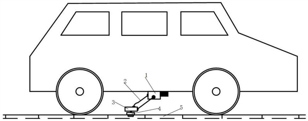
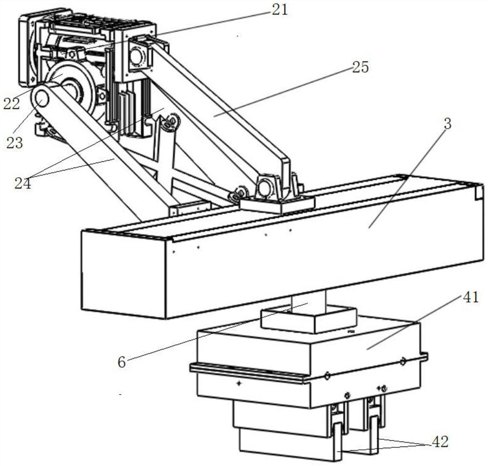
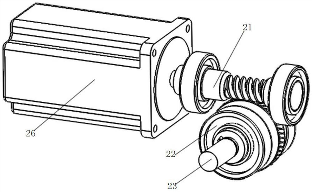
[0026] Such as figure 1 , figure 2 and Figure 6 As shown, a contact type vehicle charging device includes a lifting mechanism 2 installed on the bottom of the vehicle through an upper frame body 1, a middle frame body 3 is provided at the transmission end of the lifting mechanism 2, and a lateral movement mechanism 7 is installed on the middle frame body 3. The transmission end of the traversing mechanism 7 is connected to the pantograph 4 through the rotating slide 6, and the lifting mechanism 2 is used to drive the middle frame body 3, the traversing mechanism 7, the rotating slide 6 and the pantograph 4 to protrude toward the ground or move toward the ground as a whole. The bottom of the vehicle is folded, and the traverse mechanism 7 is used to drive the rotary slide table 6 and the pantograph 4 to move laterally along the vehicle axis as a whole. The pa...


PUM


Abstract

The invention discloses a contact type vehicle traveling charging device and a charging method thereof. The device comprises a lifting mechanism installed at the bottom of a vehicle through an upper frame body, a middle frame body is arranged at the transmission tail end of the lifting mechanism, a transverse moving mechanism is installed on the middle frame body, the transmission tail end of the transverse moving mechanism is connected with a pantograph through a rotary sliding table, the lifting mechanism is used for driving the middle frame body, the transverse moving mechanism, the rotary sliding table and the pantograph to integrally extend out of the ground or fold towards the bottom of the vehicle, the transverse moving mechanism is used for driving the rotary sliding table and the pantograph to integrally transversely move in the axial direction of the vehicle, the pantograph comprises a lower frame body, and a pair of electric brushes, an electric brush clamp and a damping assembly which are arranged on the lower frame body, the lower end of each electric brush is suspended and points to the ground, the upper portion of each electric brush is installed on the electric brush clamp, the electric brush clamp and the lower frame body are insulated and vertically matched in a sliding mode, the electric brush clamp charges a vehicle through an insulated circuit, and the damping assembly is used for keeping downward pressing and providing buffering when the electric brushes make contact with a conductor rail on the ground. According to the device and method, the vehicle can adapt to road conditions and can be stably charged during traveling.

Description

technical field [0001] The invention belongs to the field of vehicle charging, and in particular relates to a contact type vehicle charging device and a charging method thereof. Background technique [0002] At present, the battery life of electric vehicles is generally completed at charging stations or battery replacement stations. The charging speed of charging stations is slow, and the charging circuit is prone to aging, which will occupy space resources. However, there are different brands and types of batteries in battery replacement stations, which are poor in interchangeability and high in maintenance costs. , will also take up space resources. Although traveling charging can overcome the problems of charging stations and power stations, currently traveling charging is mainly used for light rail and trams. Most of the charging power lines are erected on elevated roads, which is difficult to lay on a large scale, and the application in the field of electric vehicles is...

Claims


Application Information

Patent Timeline
IPC IPC(8): B60L53/14B60L53/16
CPCB60L53/14B60L53/16Y02T10/70Y02T10/7072Y02T90/14
Inventor 徐琳王昊张长鸿胡皓然庞杰王浩宇徐楚媛李兆鹏罗泽洲王晨霖李子轩
Owner WUHAN UNIV OF TECH
Learn More