Current detection circuit

A technology of current detection circuit and current detection module, which is applied in the field of circuits and can solve problems such as low detection accuracy and complicated circuits

Pending Publication Date: 2021-09-14
SUZHOU RIGOL PRECISION ELECTRIC TECH
View PDF6 Cites 1 Cited by
  • Summary
  • Abstract
  • Description
  • Claims
  • Application Information

AI Technical Summary

Problems solved by technology

[0004] The purpose of the embodiment of the present application is to provide a current detection circuit to solve the problems of low detection accuracy and complicated circuits in existing current detection

Method used


Image

  • Current detection circuit
  • Current detection circuit
  • Current detection circuit

Examples


Embodiment Construction

[0036] The following will clearly describe the technical solutions in the embodiments of the present application with reference to the drawings in the embodiments of the present application. Obviously, the described embodiments are part of the embodiments of the present application, but not all of them. All other embodiments obtained by persons of ordinary skill in the art based on the embodiments in this application belong to the protection scope of this application.

[0037] The terms "first", "second" and the like in the specification and claims of the present application are used to distinguish similar objects, and are not used to describe a specific sequence or sequence. It should be understood that the terms so used are interchangeable under appropriate circumstances such that the embodiments of the application can be practiced in sequences other than those illustrated or described herein, and that references to "first," "second," etc. distinguish Objects are generally o...


PUM


Abstract

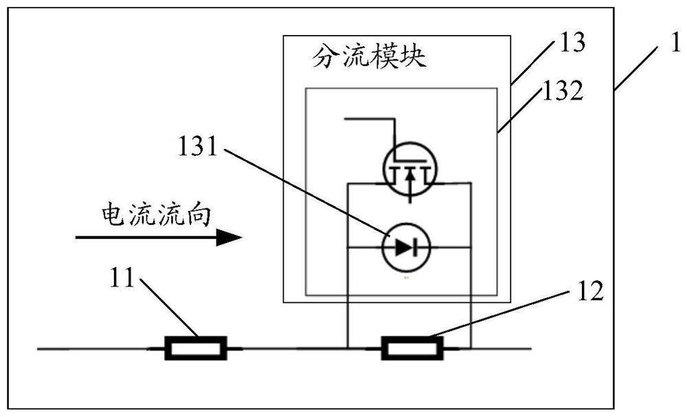
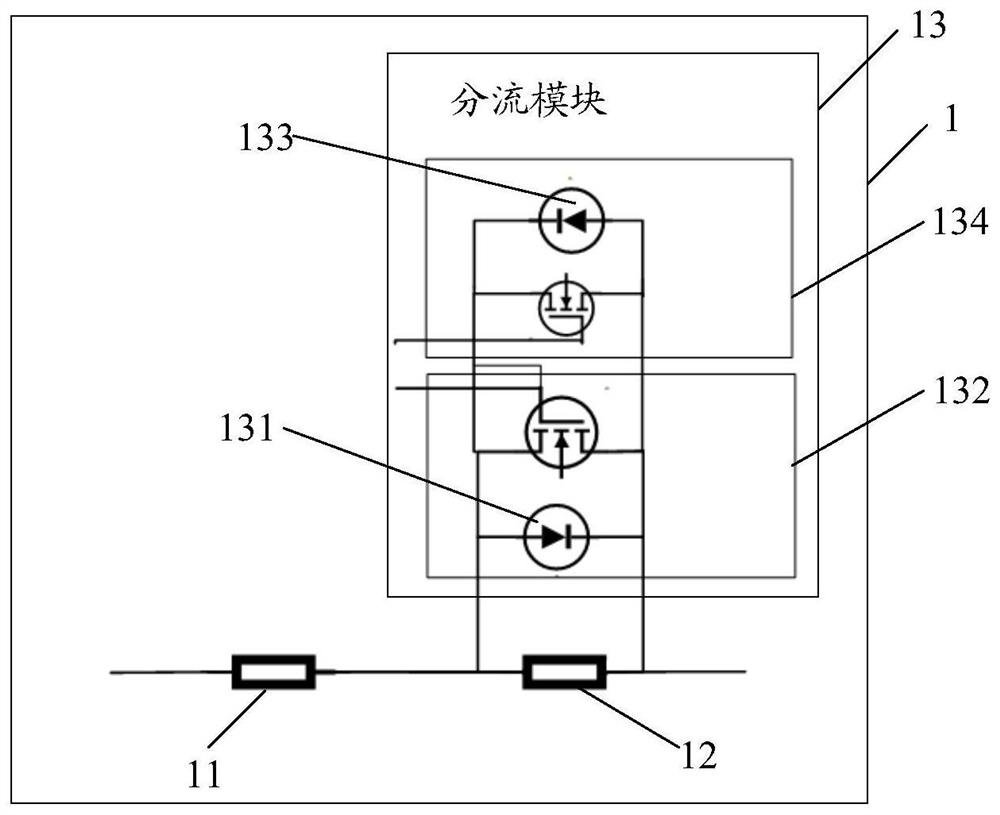
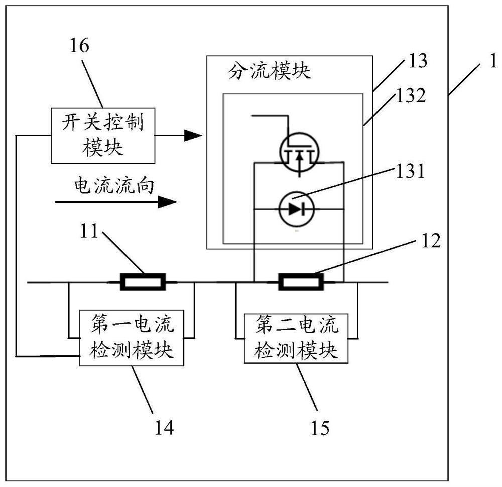
The embodiment of the invention provides a current detection circuit which comprises: a first resistor and a second resistor which are connected in series, wherein the resistance value of the first resistor is smaller than or equal to that of the second resistor; and a shunt module which is connected with the second resistor in parallel and comprises a first MOS (Metal Oxide Semiconductor) tube in which a first diode is arranged, wherein under the condition that the current flows through the first resistor and the second resistor and the flow direction of the current is the same as the conduction direction of the first diode, if the test voltage is smaller than a first preset voltage, the value of the current flowing through the second resistor is detected, and if the test voltage is greater than the first preset voltage, detecting a current value flowing through the first resistor. The test voltage is the product of the second resistor and the current, and the first preset voltage is smaller than or equal to the dead-zone voltage of the first diode. The current detection circuit solves the problem that an existing current detection circuit is complex.

Description

technical field [0001] The present application belongs to the field of circuit technology, and in particular relates to a current detection circuit. Background technique [0002] Equipment manufacturers or users usually need to know the power consumption of loads (such as mobile bracelets, mobile phones, batteries, etc.) during the entire working process, so that they can design and evaluate the usage of the load, such as evaluating life, capacity, and efficiency. [0003] At present, when performing current detection on the load, the load may have a relatively large current demand at an instant, and then only a small current is required, which may be the working current or the standby current. For conventional current detection, it is difficult to meet the load current detection requirements while maintaining detection accuracy; in addition, the existing circuit needs to connect diodes and bridge stacks in parallel, and the circuit is relatively complicated. Contents of t...

Claims


Application Information

Patent Timeline
Patent Type & Authority Applications(China)
IPC IPC(8): G01R19/00
CPCG01R19/0092
Inventor 邓晶晶王悦
Owner SUZHOU RIGOL PRECISION ELECTRIC TECH
Why Eureka
Try Eureka