
Control method and device for direct current motor and motor control system

A technology of DC motor and control method, which is applied in the direction of DC motor speed/torque control, control system, excitation or armature current control, etc., and can solve problems such as reducing the service life of DC motors, complicated control, and damage to the shaft of DC motors

Active Publication Date: 2021-09-14
QINGDAO HAIER BIOMEDICAL TECH CO LTD +1
View PDF8 Cites 1 Cited by
  • Summary
  • Abstract
  • Description
  • Claims
  • Application Information

AI Technical Summary

Problems solved by technology

[0004] The starting current of the existing DC motor will reach 6 to 8 times of the rated current when it is started at a constant speed, which will cause damage to the shaft of the DC motor and reduce the service life of the DC motor. At the same time, for the closed-loop control starting method , this solution generally requires multiple field effect transistors and sensors to implement, resulting in complex control and high cost, and it is difficult to meet the needs of the market

Method used


Image

  • Control method and device for direct current motor and motor control system
  • Control method and device for direct current motor and motor control system
  • Control method and device for direct current motor and motor control system

Examples


Embodiment Construction

[0050]In order to understand the characteristics and technical content of the embodiments of the present disclosure in more detail, the implementation of the embodiments of the present disclosure will be described in detail below in conjunction with the accompanying drawings. The attached drawings are only for reference and description, and are not intended to limit the embodiments of the present disclosure. In the following technical description, for purposes of explanation, numerous details are set forth in order to provide a thorough understanding of the disclosed embodiments. However, one or more embodiments may be practiced without these details. In other instances, well-known structures and devices may be shown simplified in order to simplify the drawings.

[0051] The terms "first", "second" and the like in the description and claims of the embodiments of the present disclosure and the above drawings are used to distinguish similar objects, and are not necessarily used ...


PUM


Abstract

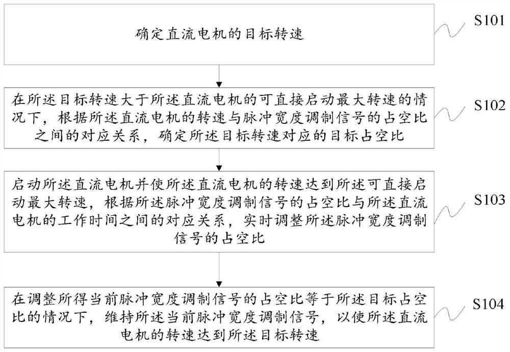
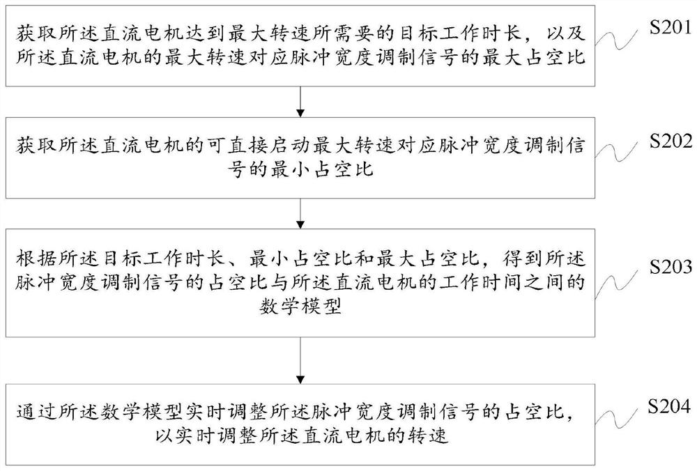
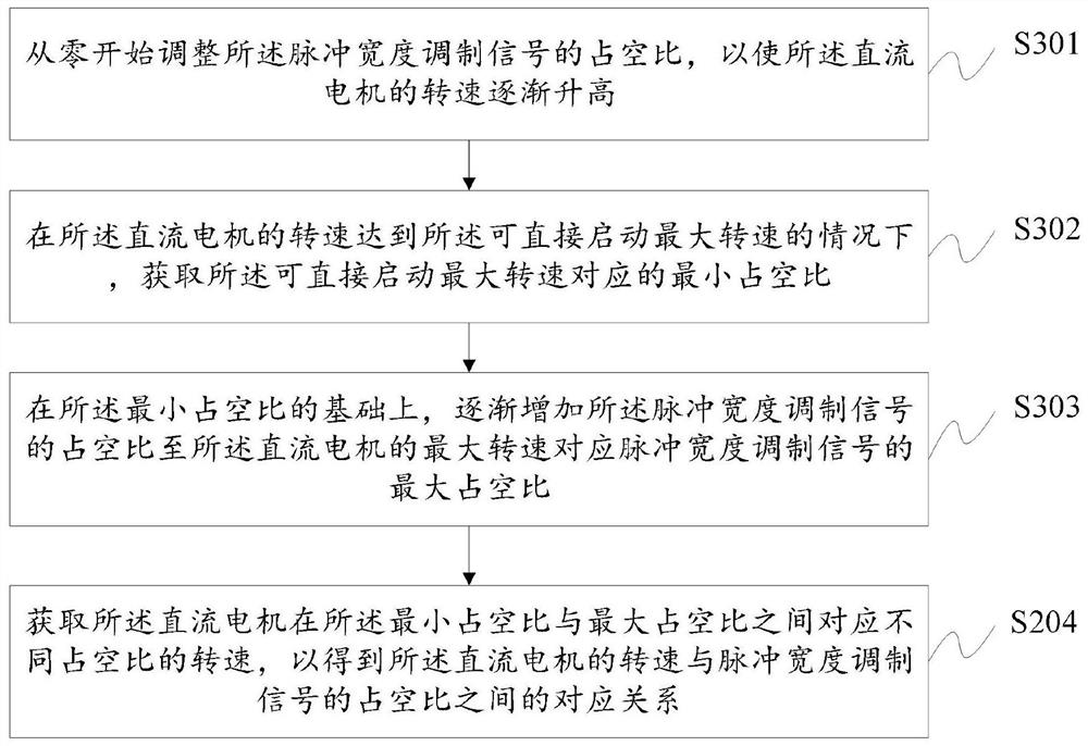
The invention relates to the technical field of motor driving, and discloses a control method for a direct current motor, which comprises the steps of determining a target rotating speed of the direct current motor; determining a target duty ratio corresponding to the target rotating speed according to a corresponding relation between the rotating speed of the direct current motor and the duty ratio of a pulse width modulation signal under the condition that the target rotating speed is greater than the maximum rotating speed of the direct current motor capable of being directly started; starting the direct current motor, enabling the rotating speed of the direct current motor to reach the maximum rotating speed capable of being directly started, and adjusting the duty ratio of the pulse width modulation signal in real time according to the corresponding relation between the duty ratio of the pulse width modulation signal and the working time of the direct current motor; and under the condition that the duty ratio of the obtained current pulse width modulation signal is adjusted to be equal to the target duty ratio, maintaining the current pulse width modulation signal so as to enable the rotating speed of the direct current motor to reach the target rotating speed.

Description

technical field [0001] The present application relates to the technical field of motor drive control, for example, to a control method, device and motor control system for a DC motor. Background technique [0002] At present, common centrifuges on the market, such as handheld centrifuges, have the characteristics of small size and low price, and their centrifugal force is mainly provided by the operation of a DC motor. Centrifuges generally use a constant-speed startup method, that is, they can be started directly by providing a fixed voltage, but this solution is only suitable for centrifuges with low speed and low load. For high-speed centrifuges, they cannot be started directly. Generally, closed-loop control is used to start the centrifuge, that is, the duty cycle of the controller output is adjusted through the real-time speed feedback of the speed sensor. [0003] In the process of implementing the embodiments of the present disclosure, it is found that at least the f...

Claims


Application Information

Patent Timeline
Patent Type & Authority Applications(China)
IPC IPC(8): H02P7/29
CPCH02P7/2913
Inventor 段泽鹏陈欢胡伟鞠焕文王潘飞宋述飞
Owner QINGDAO HAIER BIOMEDICAL TECH CO LTD
Learn More