Multifunctional agricultural machine
An agricultural machinery and multi-functional technology, applied in agricultural machinery and implements, agriculture, excavators, etc., can solve problems such as inability to remove soil, and achieve the effects of reducing labor intensity, blockage, and workload.
- Summary
- Abstract
- Description
- Claims
- Application Information
AI Technical Summary
Problems solved by technology
Method used
Image
Examples
Embodiment 1
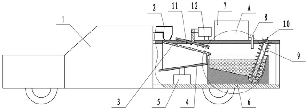
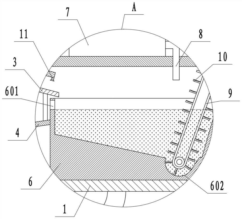
[0037] Embodiment one is basically as attached figure 1 Shown: a multifunctional agricultural machine, including a harvester 1 and a discharge part connected to the harvester 1, the discharge part includes a discharge hopper 2 for discharging the agricultural products harvested by the harvester 1, and the harvester 1 is movable The vibrating screen 3 is connected to the bottom of the discharge hopper 2, and the vibrating screen 3 is provided with screen holes. Plate 4, the bottom of vibration plate 4 is fixedly connected with vibration motor 5 by screw, and vibration motor 5 is fixedly connected on the harvester 1 by screw.
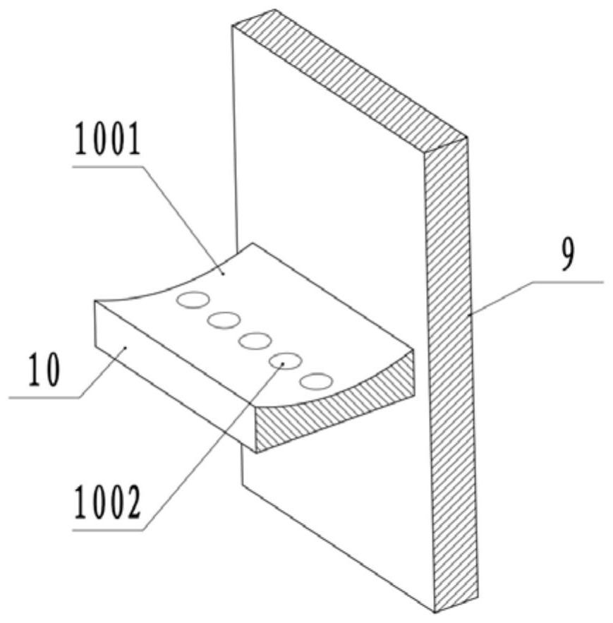
[0038] The right side of the vibrating screen 3 is provided with a first cleaning mechanism for receiving agricultural products dropped on the vibrating screen 3. In this embodiment, the first cleaning mechanism includes a cleaning tank 6 and a water adding part connected to the cleaning tank 6. The water adding part Including a water tank 7 and a water-...
Embodiment 2
[0047] The difference between embodiment two and embodiment one is: as Figure 4 As shown, in this embodiment, a cleaning roller 13 is rotatably connected in the cleaning tank 6, and a brush 14 is fixed on the cleaning roller 13 by bonding. The brush 14 is arranged along the circumferential direction of the cleaning roller 13, and the brush 14 A cleaning gap is provided between the bottom of the 14 and the bottom of the cleaning tank 6, and the top of the hairbrush 14 protrudes above the water surface in the cleaning tank 6, and the cleaning tank 6 is fixedly connected with a second wheel for driving the cleaning roller 13 to rotate by bolts. motor( image 3 The second drive motor is not shown in the figure), and the drive motor can be used to drive the cleaning roller 13 along the image 3 Rotate counterclockwise, the brush 14 will wash the agricultural products at the bottom of the cleaning tank 6, so that the soil on the agricultural products can be cleaned more thoroughly...
Embodiment 3
[0049] The difference between embodiment three and embodiment two is: as Figure 5 As shown, in the cleaning tank 6, a vertically arranged partition 15 is fixedly connected with screws, and the partition 15 is provided with a mesh for the flow of water in the cleaning tank 6, and the partition 15 is located between the conveyor belt 9 and the vibrating screen 3, And the spacer 15 is positioned at the right side of the hairbrush 14, the top of the spacer 15 protrudes above the water surface in the cleaning tank 6, the bottom of the dividing plate 10 is located in the cleaning tank 6, and the bottom of the dividing plate 10 is in contact with the cleaning tank 6. A transmission gap is provided between the bottoms to prevent the partition plate 10 from blocking the sliding of the agricultural products in the cleaning tank 6 . In this embodiment, by setting the screen 15, the impurities on the left side of the screen 15 in the cleaning tank 6 can be completely prevented from enter...
PUM
 Abstract
Description
Claims
Application Information
 - R&D
- Intellectual Property
- Life Sciences
- Materials
- Tech Scout
- Unparalleled Data Quality
- Higher Quality Content
- 60% Fewer Hallucinations
Browse by: Latest US Patents, China's latest patents, Technical Efficacy Thesaurus, Application Domain, Technology Topic, Popular Technical Reports.
© 2025 PatSnap. All rights reserved.Legal|Privacy policy|Modern Slavery Act Transparency Statement|Sitemap|About US| Contact US: help@patsnap.com


