
Energy-saving injection molding machine with heat recovery function

A heat recovery and injection molding machine technology, applied in the field of plastic molding equipment, can solve the problems of waste heat waste, huge power consumption, low energy conversion efficiency, etc., achieve precise temperature control, increase the upper limit of heating temperature, and improve energy utilization efficiency.

Pending Publication Date: 2021-09-17
BEIJING UNIV OF CHEM TECH
View PDF1 Cites 1 Cited by
  • Summary
  • Abstract
  • Description
  • Claims
  • Application Information

AI Technical Summary

Problems solved by technology

High-efficiency production requires that the molding cycle be as short as possible, and the mold needs to be continuously cooled so that the plastic can be solidified and formed as soon as possible, which leads to a lot of waste heat being wasted. It needs to consume a huge amount of electric energy, so the energy utilization efficiency of this working mode is low
[0003] In order to improve the energy utilization efficiency of the injection molding machine, CN208788935U uses a thermal battery to recover the excess heat emitted by the mold temperature controller, and then provides it to the electronic system of the injection molding machine. However, the current thermal battery technology is not yet mature, and the energy conversion efficiency is very low. A very small amount of energy is recovered; CN109664461A introduces the circulating cooling water for cooling the head of the injection molding machine into the storage tank, and uses the heat of the circulating water to preheat the plastic raw materials in the storage tank, thereby achieving the purpose of energy saving, but because the temperature of the circulating water is generally low , this method has a limited preheating effect on raw materials and can only recover a small amount of energy

Method used


Image

  • Energy-saving injection molding machine with heat recovery function
  • Energy-saving injection molding machine with heat recovery function
  • Energy-saving injection molding machine with heat recovery function

Examples


Embodiment Construction

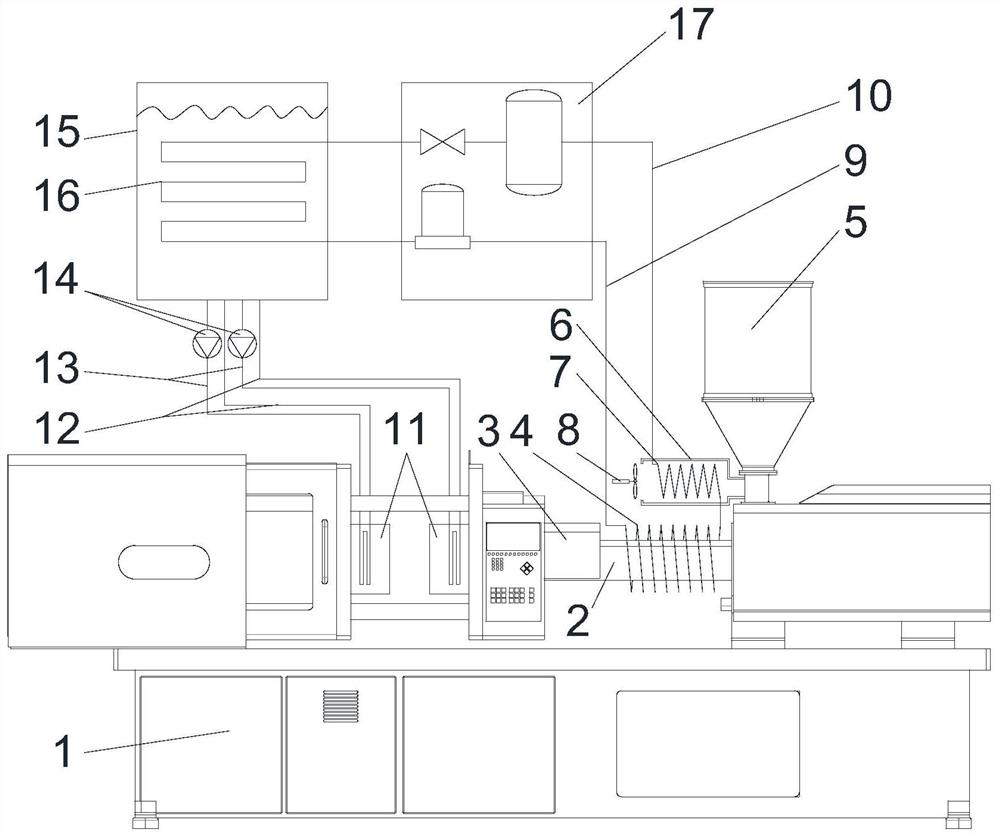
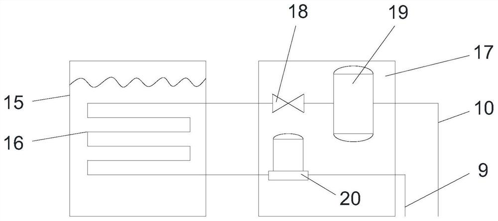
[0016] The present invention proposes an energy-saving injection molding machine with heat recovery function, such as figure 1 and figure 2 As shown, the device mainly includes: injection molding machine main body 1, barrel 2, heater 3, plasticizing coil 4, hopper 5, heat exchange cylinder 6, heat exchange coil 7, fan 8, heating pipe 9, heating return Pipe 10, mold 11, cooling return pipe 12, cooling pipe 13, circulation pump 14, water tank 15, water tank coil 16, heat pump 17, throttle valve 18, liquid tank 19 and compressor 20. Among them, the main body 1 of the injection molding machine is a general-purpose injection molding machine, the left side is the clamping mechanism, and the right side is the plasticizing mechanism. Except for the structure specified in this patent, the rest of the structure is the same as the general injection molding machine; the barrel 2 is the injection molding machine. The screw barrel of the main body 1; the heater 3 is a general-purpose elec...


PUM


Abstract

The invention provides an energy-saving injection molding machine with a heat recovery function. The energy-saving injection molding machine mainly comprises an injection molding machine main body, a charging barrel, a heater, a plasticizing coil pipe, a hopper, a heat exchange barrel, a heat exchange coil pipe, a fan, a heating pipe, a heating return pipe, a mold, a cooling return pipe, a cooling pipe, a circulating pump, a water tank, a water tank coil pipe, a heat pump, a throttle valve, a liquid tank and a compressor. Based on the heat pump principle, firstly, heat, transferred to a mold, of materials is absorbed by cooling water, then the heat of the cooling water is transferred to a plasticizing system through the heat pump, the quality of the heat is improved, and the heat is used for plasticizing raw material particles, so that recycling of heat energy is achieved; and the heat pump also plays a role in cooling the cooling water, so that the cooling efficiency of the mold is improved. Waste heat after plasticization is also used for preheating plastic raw material particles, so that the energy utilization efficiency is further improved; the multi-stage heat pumps are connected in series; the purpose of increasing the heating temperature upper limit is achieved; and the opening degree of a throttling valve is adjusted, the medium pressure and boiling point are changed, and the purpose of accurate temperature control is achieved.

Description

technical field [0001] The invention relates to the field of plastic molding equipment, in particular to an energy-saving injection molding machine with heat recovery function. Background technique [0002] Injection molding machine is the most important equipment for mass production of plastic products with complex structures, and occupies an important position in the national economy. High-efficiency production requires that the molding cycle be as short as possible, and the mold needs to be continuously cooled so that the plastic can be solidified and formed as soon as possible, which leads to a lot of waste heat being wasted. It needs to consume a huge amount of electric energy, so the energy utilization efficiency of this working mode is low. [0003] In order to improve the energy utilization efficiency of the injection molding machine, CN208788935U uses a thermal battery to recover the excess heat emitted by the mold temperature controller, and then provides it to th...

Claims


Application Information

Patent Timeline
Patent Type & Authority Applications(China)
IPC IPC(8): B29C45/72B29C45/73B29C45/03B29C45/17B29B13/02B29C45/78
CPCB29C45/72B29C45/73B29C45/03B29C45/17B29B13/02B29C45/78B29C2045/7292B29C2945/76531Y02P70/10
Inventor 杨卫民宋乐谢鹏程丁玉梅
Owner BEIJING UNIV OF CHEM TECH
Learn More