Processing, conveying and cooling equipment for gypsum production line

A cooling equipment and production line technology, applied in lighting and heating equipment, conveyors, refrigerators, etc., can solve the problems of difficult to achieve rapid cooling of gypsum, low cooling speed, waste of raw materials, etc., to reduce the loss of raw materials and increase cooling Time, the effect of good quick cooling effect

Active Publication Date: 2021-09-17
江苏思克赛斯机械制造有限公司
View PDF7 Cites 0 Cited by
  • Summary
  • Abstract
  • Description
  • Claims
  • Application Information

AI Technical Summary

Problems solved by technology

[0002] The use of gypsum as a building material is mainly to convert the existing gypsum in various forms into hemihydrate gypsum. In this process, the gypsum needs to be calcined first and then cooled down. It is difficult to realize from the existing gypsum processing line Rapid cooling of gypsum from calciner
[0003] After searching, the Chinese authorized patent CN106145724B discloses a mixing, conveying and cooling device for a gypsum processing production line, which belongs to the field of building materials, including a fan, an air supply distributor and a humidifying device, an air supply pipe, a conveying mixer shell, a liner, and conveying and stirring device, air cover, and air outlet pipe; the fan is installed on one side of the conveying mixer, and is connected with the air supply distributor and humidification device through the air supply pipe. However, in actual use, there are also the following defects: only cooling by air cooling is not effective under the condition of rapid cooling, and when this prior art is used, it will not be treated in close contact with gypsum. The direct exhaust of the exhaust gas will carry some gypsum residues, which not only wastes raw materials, but also may cause pollution

Method used


Image

  • Processing, conveying and cooling equipment for gypsum production line
  • Processing, conveying and cooling equipment for gypsum production line
  • Processing, conveying and cooling equipment for gypsum production line

Examples


Embodiment Construction

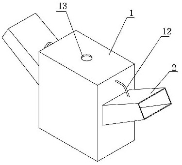
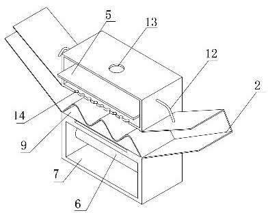
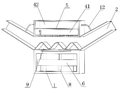
[0022] refer to Figure 1-3 , a processing and conveying cooling equipment for a gypsum production line, comprising a cooling box 1 and a conveying bucket 2, the conveying bucket 2 is provided with a conveyor belt for gypsum transportation, the conveying bucket 2 is sealed and runs through the two side walls of the cooling box 1, and the conveying bucket 2 The part located in the cooling box 1 adopts a wave-shaped structure, which increases the path of the conveying bucket 2 during transportation, thereby prolonging the time for the gypsum to stay in the cooling box 1. The part of the conveying bucket 2 located outside the cooling box 1 adopts a middle low , a funnel-shaped structure with high sides, the conveying bucket 2 is located on the upper wall of the cooling box 1, and a cooling port 3 is opened through it, and the part of the cooling box 1 above the cooling port 3 is provided with a processing space, and the cooling box 1 is located on the conveying bucket 2 The lower...


PUM


Abstract

The invention discloses processing, conveying and cooling equipment for a gypsum production line. The processing, conveying and cooling equipment comprises a cooling box and a conveying hopper; a conveying belt used for conveying gypsum is arranged in the conveying hopper, the conveying hopper penetrates through the two side walls of the cooling box in a sealed mode, and a cooling through opening is formed in the position, located on the upper wall of the cooling box, of the conveying hopper in a penetrating mode; a processing space is formed in the part, located above the cooling through opening, of the cooling box; a connecting space is formed in the part, located below the conveying hopper, of the cooling box; a sealing plate is connected into the processing space in a sealed mode; and a cold air storage cavity is formed in the space, located below the sealing plate, of the processing space; the space, located above the sealing plate, of the processing space is arranged to be an excess material recycling cavity; a cooling structure is arranged in the cold air storage cavity; and a recycling structure is connected into the excess material recycling cavity. The equipment has the advantages that the rapid cooling process is better achieved, the tail gas absorption effect is achieved, and raw material waste and air pollution are avoided.

Description

technical field [0001] The invention relates to the technical field of building material processing, in particular to processing, conveying and cooling equipment for a gypsum production line. Background technique [0002] The use of gypsum as a building material is mainly to convert the existing gypsum in various forms into hemihydrate gypsum. In this process, the gypsum needs to be calcined first and then cooled down. It is difficult to realize from the existing gypsum processing line Rapid cooling of gypsum coming out of the calciner. [0003] After searching, the Chinese authorized patent CN106145724B discloses a mixing, conveying and cooling device for a gypsum processing production line, which belongs to the field of building materials, including a fan, an air supply distributor and a humidifying device, an air supply pipe, a conveying mixer shell, a liner, and conveying and stirring device, air cover, and air outlet pipe; the fan is installed on one side of the convey...

Claims


Application Information

Patent Timeline
Patent Type & Authority Applications(China)
IPC IPC(8): F25B9/04B65G15/42
CPCF25B9/04B65G15/42
Inventor 奚乐
Owner 江苏思克赛斯机械制造有限公司
Why Eureka
Try Eureka