Resonant accelerometer structure with low temperature sensitivity

An accelerometer, sensitive technology, applied in the direction of velocity/acceleration/shock measurement, measurement of acceleration, gyro effect for velocity measurement, etc., can solve the problem of inability to eliminate temperature drift, accelerometer frequency change, inconsistent drift, resonator drift, etc. problems, to eliminate cross-sensitivity, improve temperature performance, and eliminate frequency drift

Pending Publication Date: 2021-09-17
NANJING INST OF TECH
View PDF1 Cites 0 Cited by
  • Summary
  • Abstract
  • Description
  • Claims
  • Application Information

AI Technical Summary

Problems solved by technology

For example, the application publication number in the prior art is CN111812355A, which discloses a silicon micro-resonant accelerometer with low stress sensitivity, specifically discloses a double-ended fixed tuning fork resonator, a micro-lever amplifying mechanism, and a mass block, which has a simple structure and temperature stability. Good, but the two resonators are not in adjacent positions, and the thermal stresses generated by the two resonators are different due to the different temperatures of the positions, which makes the drift of the resonant frequency of the two resonators inconsistent, and the temperature drift caused by the two resonators cannot be eliminated. Accelerometer Frequency Variation Effect
[0004] In addition, the working sensitive object of the accelerometer resonator is the axial force, and the non-axial force is easy to cause the drift of the resonator, which brings the problem of cross sensitivity
In the existing accelerometer structure, there is no clear direction-defining structure to ensure the unidirectional sensitivity of the resonator

Method used


Image

  • Resonant accelerometer structure with low temperature sensitivity
  • Resonant accelerometer structure with low temperature sensitivity
  • Resonant accelerometer structure with low temperature sensitivity

Examples


Embodiment Construction

[0019] The preferred embodiments of the present invention will be described in detail below in conjunction with the accompanying drawings and examples, so that the advantages and features of the present invention can be more easily understood by those skilled in the art, so as to define the protection scope of the present invention more clearly.

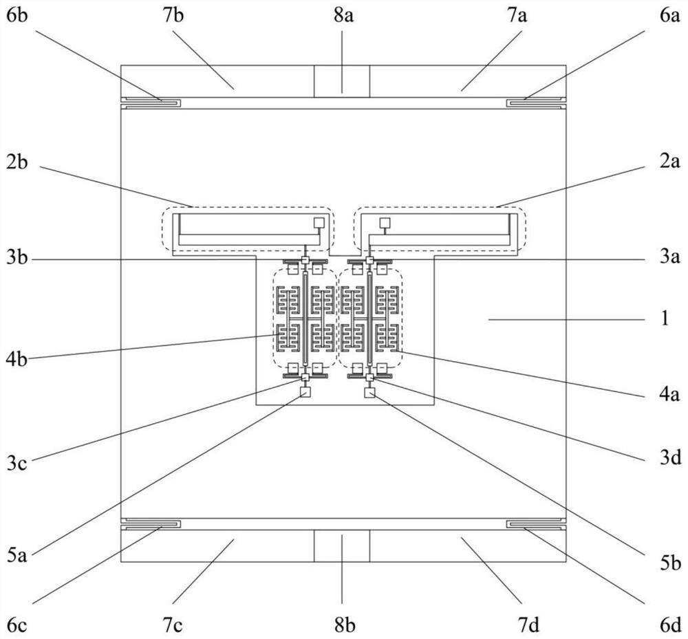
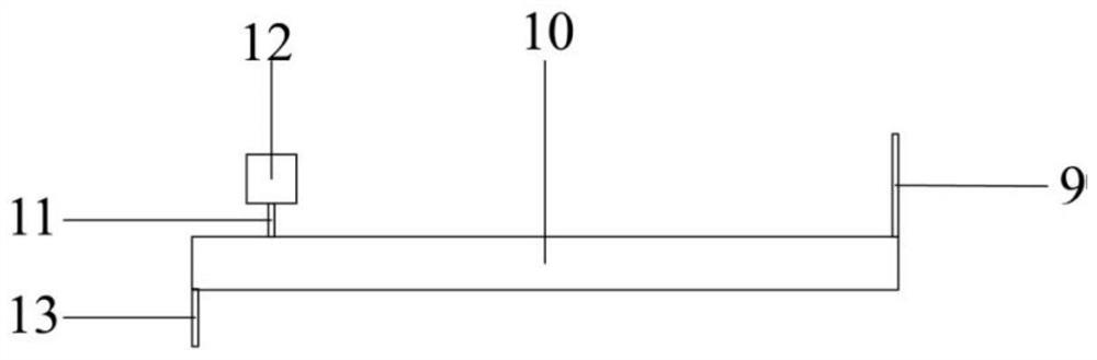
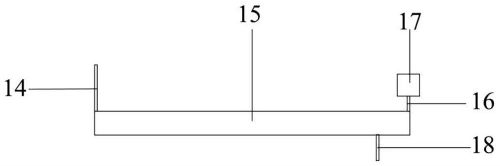
[0020] like Figure 1-5 As shown, the present invention is a low temperature sensitivity resonant accelerometer structure, the resonant accelerometer includes a glass base layer, a lead layer, a bonding layer and a silicon structure layer connected in sequence, wherein the lead layer is a metal layer, silicon The structural layer includes sensitive mass 1, two primary lever amplification mechanisms, four direction limiting mechanisms, two double-ended fixed tuning fork resonators, two resonator anchor points, four supporting folding beams, four fixed frames and two An anchor point for the overall structure. Wherein, the four directi...


PUM


Abstract

The invention discloses a resonant accelerometer structure with low temperature sensitivity, wherein the resonant accelerometer structure comprises a silicon structure layer; the silicon structure layer comprises a sensitive mass block, first-stage lever amplification mechanisms, direction limiting mechanisms and two double-end fixed tuning fork resonators, and the two double-end fixed tuning fork resonators are adjacently arranged; and one end of each double-end fixed tuning fork resonator is connected with one first-stage lever amplification mechanism through one direction limiting mechanism, the other end of each double-end fixed tuning fork resonator is connected with one resonator anchor point through one direction limiting mechanism, the sensitive mass block is connected with fixed frames through the supporting folding beams, and an integral structure anchor point is arranged between each two fixed frames. The first-stage lever amplification mechanisms connected with the two double-end fixed tuning fork resonators are in two different forms and are symmetrically arranged to form differential output of an accelerometer. According to the invention, the cross sensitivity of acceleration signals can be eliminated, the frequency drift of the accelerometer caused by working temperature change is reduced or even eliminated, and the temperature performance of the accelerometer is improved.

Description

technical field [0001] The invention relates to the fields of micro-mechanical electronic systems (MEMS) and micro-inertial devices, in particular to a low-temperature-sensitivity resonant accelerometer structure. Background technique [0002] Silicon microresonant accelerometer is a typical MEMS (Micro Electromechanical system, micro-electromechanical system) inertial sensor. Its processing technology is compatible with microelectronic processing technology and can be mass-produced. It has the characteristics of low power consumption, high reliability, easy intelligence and digitalization, and can meet harsh environment applications. It is one of the hot directions in the development of accelerometers today. It has important military value and broad civilian prospects. [0003] At present, the existing silicon microresonant accelerometers are generally composed of a resonator, a mass and a glass substrate. The two resonators have the same size and are symmetrically arranged...

Claims


Application Information

Patent Timeline
Patent Type & Authority Applications(China)
IPC IPC(8): G01C19/5621G01P15/097
CPCG01C19/5621G01P15/097G01P2015/0862
Inventor 高阳孟琳刘洋洋张嘉超焦良葆曹雪虹
Owner NANJING INST OF TECH
Why Eureka
Try Eureka