
Power semiconductor device packaging structure and manufacturing method thereof

A technology for power semiconductor and device packaging, applied in semiconductor devices, semiconductor/solid-state device components, electric solid-state devices, etc. Effects of damage, reduction of deformation stress, and improvement of reliability

Active Publication Date: 2021-12-14
深圳真茂佳半导体有限公司
View PDF9 Cites 0 Cited by
  • Summary
  • Abstract
  • Description
  • Claims
  • Application Information

AI Technical Summary

Problems solved by technology

The technical prejudice under the relevant patents is that the gate contact pad, source contact pad and drain contact pad are all arranged on the front side, and the drain contact pad is located on the front side. The necessary deep trench excavation and corresponding isolation will increase the difficulty of chip manufacturing and production process flow, and occupy the effective area of ​​the on-chip transistor

Method used


Image

  • Power semiconductor device packaging structure and manufacturing method thereof
  • Power semiconductor device packaging structure and manufacturing method thereof
  • Power semiconductor device packaging structure and manufacturing method thereof

Examples


Embodiment Construction

[0065] The technical solutions in the embodiments of the present invention will be clearly and completely described below in conjunction with the accompanying drawings in the embodiments of the present invention. Apparently, the described embodiments are only part of the embodiments for understanding the inventive concepts of the present invention, and cannot represent All the embodiments are not explained as the only embodiment. Based on the embodiments of the present invention, all other embodiments obtained by persons of ordinary skill in the art on the premise of understanding the inventive concepts of the present invention fall within the protection scope of the present invention.

[0066] It should be noted that if there is a directional indication (such as up, down, left, right, front, back...) in the embodiment of the present invention, the directional indication is only used to explain the relationship between the components in a certain posture. If the specific postu...


PUM


Abstract

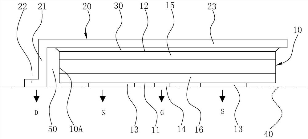
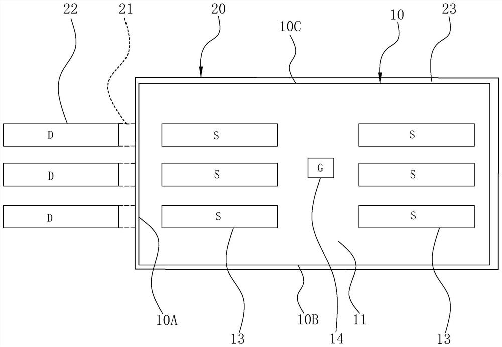
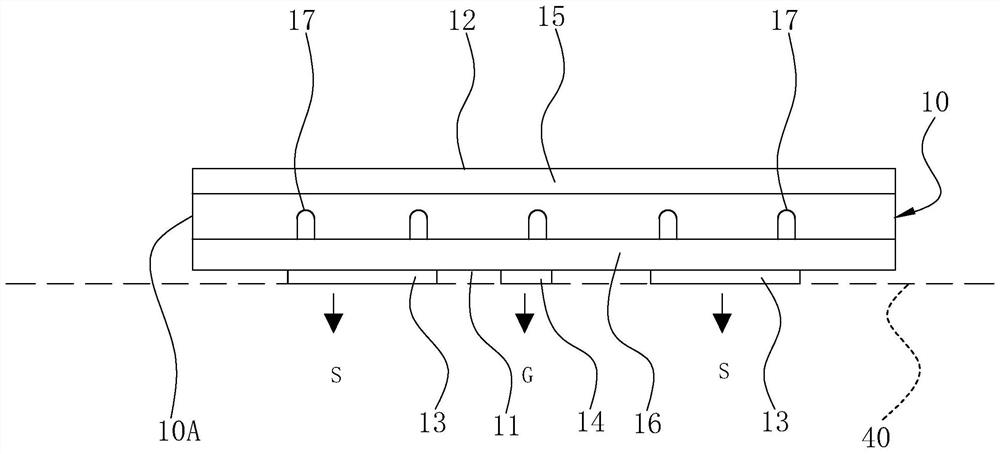
The invention relates to a packaging structure of a power semiconductor device and a manufacturing method thereof. The structure includes a chip body and a heat dissipation carrier. A source pad and a gate pad are arranged on the processing surface of the chip body, and a drain layer is arranged on the back surface; The heat sink is attached to the back of the chip body and electrically coupled to the drain layer. The heat sink has integrally extended side legs, which are bent from the back through the side of the chip body to the bonding plane where the source pad and the gate pad are located. The side leg is formed as a drain pad at one end of the bonding plane; the side leg maintains a gap with the side of the chip body, so that the drain pad is movable relative to the source pad and the gate pad. The encapsulation structure provided by the invention reduces the difficulty of chip manufacturing of the power semiconductor device and reduces the production process, and improves the effect of the transistor effective area of ​​the chip.

Description

technical field [0001] The invention relates to the technical field of packaging of power semiconductor devices, in particular to a packaging structure of a power semiconductor device and a manufacturing method thereof. Background technique [0002] Existing power semiconductor devices generally adopt MOSFET (metal-oxide-semiconductor field-effect transistor) architecture, and the source pad, drain pad and gate pad of the metal part are all set on the processing surface of the chip. In use, it can be electrically connected to the circuit board. In the structure of the MOSFET chip in the early stage of semiconductor manufacturing, the source pad and gate pad are on the front side of the wafer, and the drain layer is on the back side of the wafer. In order to lead the drain layer To the same side as the source pad, it is necessary to dig a slot on the chip to connect the drain layer on the back with the drain pad contact on the front. Digging deep grooves and the corresponding...

Claims


Application Information

Patent Timeline
Patent Type & Authority Patents(China)
IPC IPC(8): H01L23/31H01L23/367H01L23/373
CPCH01L23/31H01L23/367H01L23/3736
Inventor 谢文华任炜强
Owner 深圳真茂佳半导体有限公司
Learn More