Electric connector

An electrical connector and electrical connection technology, which is applied in the direction of conductive connection, connection, fixed connection, etc., can solve problems such as solder ball cracking, poor contact, and affecting signal transmission of signal terminals, so as to reduce rotation or offset and improve High-frequency performance, not easy to shake the effect

Active Publication Date: 2021-09-17
中山得意电子有限公司
View PDF10 Cites 0 Cited by
  • Summary
  • Abstract
  • Description
  • Claims
  • Application Information

AI Technical Summary

Problems solved by technology

During use, the soldering portion of the signal terminal of the electrical connector may be subjected to external force and rotate or shift relative to the solder ball, for example, the electrical connector is repeatedly plugged and pulled out or used Collision with other objects during the process may easily cause cracks in the solder balls of the soldering portion of the signal terminal, resulting in poor contact between the signal terminal and the circuit board, thereby affecting the signal of the electrical connector. terminal for signal transmission

Method used


Image

  • Electric connector
  • Electric connector
  • Electric connector

Examples


Embodiment Construction

[0033] In order to facilitate a better understanding of the purpose, structure, features and effects of the present invention, the present invention will now be further described with reference to the accompanying drawings and specific embodiments.

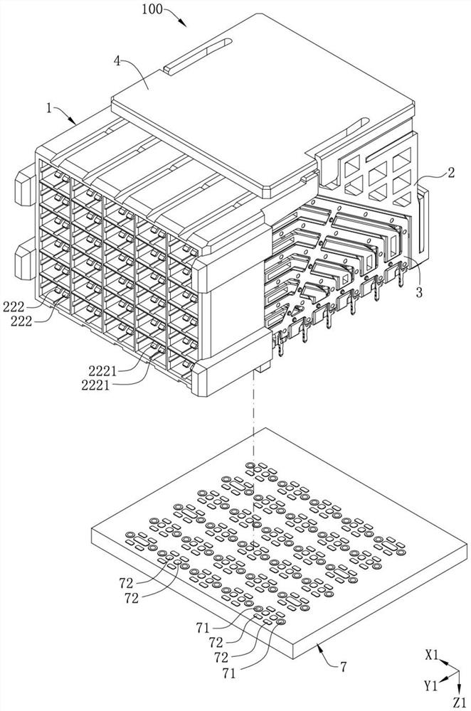
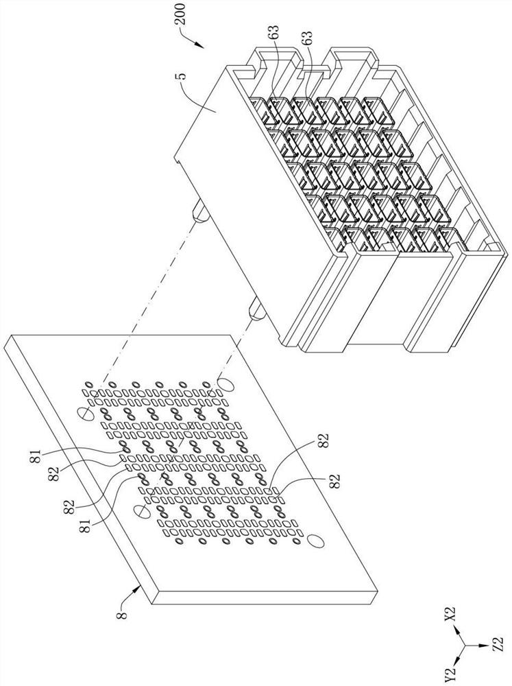
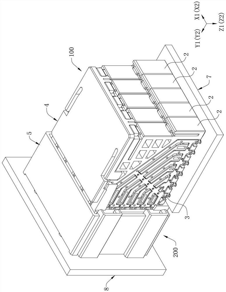
[0034] see Figure 1 to Figure 3 , which are two electrical connectors that are butted against each other provided in the embodiment of the present invention, and the two electrical connectors include a first connector 100 and a second connector 200 . Each of the two electrical connectors is electrically connected to a substrate, wherein the first connector 100 is electrically connected to a first substrate 7 , and the second connector 200 is electrically connected to a second substrate 8 connect. Both of the electrical connectors have corresponding terminal assemblies, each of the terminal assemblies has an insulating block, a pair of signal terminals and a shielding shell, and each of the signal terminals has a contact portion,...


PUM


Abstract

The invention discloses an electric connector, and the electric connector comprises at least one terminal assembly, and the terminal assembly comprises an insulating block; a pair of signal terminals which are fixed on the insulating block, wherein the surface type welding parts of the pair of signal terminals are arranged along a first direction, each surface type welding part is provided with a welding surface facing a second direction, the second direction is perpendicular to the first direction, the welding surfaces are used for fixing a solder ball in advance before the electric connector is welded with a substrate, the solder ball is arranged on the surface type welding parts of the pair of signal terminals, and each surface type welding part is welded on the surface of the substrate through a solder ball; and a shielding shell which is provided with two jack-type tail parts which are electrically connected with the through holes of the substrate, wherein the two jack-type tail parts are respectively positioned on two sides of the pair of surface-type welding parts along the first direction. According to the invention, the coplanarity of the signal terminals can be improved, the occupation of the wiring space of the substrate by the signal terminals can be reduced, and the risk of tin cracks of the solder balls can be reduced.

Description

【Technical field】 [0001] The invention relates to an electrical connector, in particular to an electrical connector in which the tin balls welded by the surface-type welding parts of the signal terminals are not prone to tin cracks. 【Background technique】 [0002] A conventional electrical connector includes a plurality of pairs of signal terminals, and the soldering portion of each of the signal terminals is soldered to the surface of the circuit board by solder balls. During use, the soldered portion of the signal terminal of the electrical connector may be rotated or shifted relative to the solder ball by external forces, for example, the electrical connector is subjected to multiple insertions and removals, or the use of During the process, the collision with other objects will easily cause the solder balls of the soldering parts of the signal terminals to crack, resulting in poor contact between the signal terminals and the circuit board, thereby affecting the signal of...

Claims


Application Information

Patent Timeline
Patent Type & Authority Applications(China)
IPC IPC(8): H01R12/57H01R4/02H01R13/648H01R13/502H01R13/646H01R13/02H01R13/40
CPCH01R12/57H01R4/029H01R13/648H01R13/502H01R13/646H01R13/02H01R13/40
Inventor 何志立张文昌
Owner 中山得意电子有限公司
Why Eureka
Try Eureka