Eureka AIR delivers breakthrough ideas for toughest innovation challenges, trusted by R&D personnel around the world.

Welding device for hairpin motor coil

A welding device and coil technology, applied in auxiliary devices, welding equipment, welding equipment, etc., can solve the problem of affecting product quality, difficulty in ensuring the final position of the end of the flat wire group, and difficulty in ensuring that each end of the wire moves to the required position, etc. problem, to achieve the effect that the quality is not easy

Pending Publication Date: 2021-09-21
深圳市合利士智能装备有限公司
View PDF0 Cites 3 Cited by
  • Summary
  • Abstract
  • Description
  • Claims
  • Application Information

AI Technical Summary

Problems solved by technology

[0004] In view of the above-mentioned related technologies, the inventor believes that it is difficult to ensure that the position of each thread end moves to the required position when manually positioning the thread ends of the flat thread group, which makes it difficult to guarantee the final position of the thread ends of the flat thread group, thus Affect the quality of welded products

Method used


Image

  • Welding device for hairpin motor coil
  • Welding device for hairpin motor coil
  • Welding device for hairpin motor coil

Examples


Embodiment Construction

[0043] The present application will be further described below with reference to the accompanying drawings.

[0044] The welding apparatus of a card motor coil disclosed herein can automatically position the wire of the flat line group by mechanical structure, so that the positioning of the wire head is more accurate, thereby improving the mass of the processed partial flat line group.

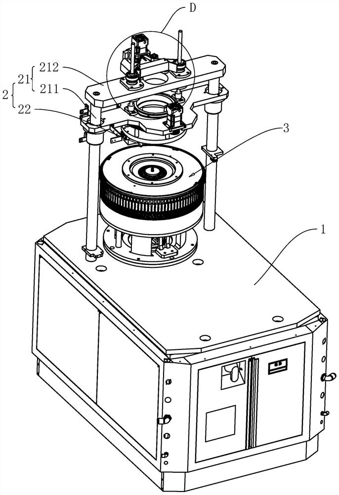
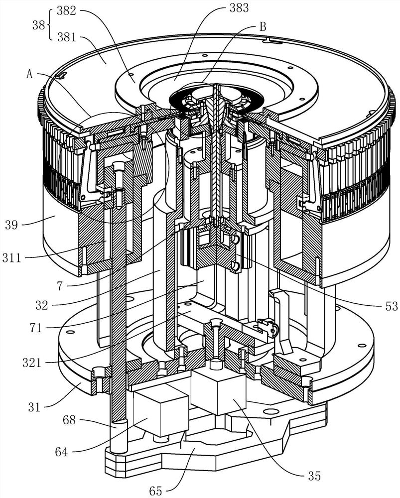
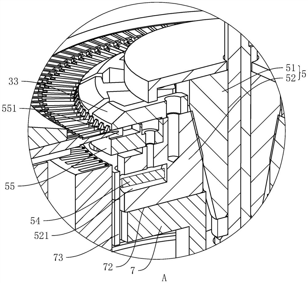
[0045] like figure 1 As shown, including the frame body 1, the welding mechanism 2 provided on the frame body 1 and a clamp 3 that positions the stator. like figure 2 with image 3 As shown, the jig 3 includes a base 31 set in a cylindrical and an upper opening, and the coaxial is disposed in the lumen of the base 31 and is used to hold a top material cover 32 of the positioning stator, and a number of internal blocks 33 of the line head of the flat line group. And several outer blocks 34. The base 31 is fixed to the end surface of the frame body 1 using a bolt, and the lower end thereof is axially...


PUM


Abstract

The invention relates to a welding device for a hairpin motor coil. The welding device comprises a frame body, a welding mechanism and a clamp. The welding mechanism comprises a support and a welding piece, wherein the support is further connected with a welding driving piece driving the welding piece to move, and the driving end of the welding driving mechanism is connected with the welding piece. The clamp comprises a base, a material ejecting sleeve, a plurality of inner pressing blocks and a plurality of outer pressing blocks, wherein a mandrel sleeve is arranged in the material ejecting sleeve and connected with the base, the inner pressing blocks are connected to the upper end face of the mandrel sleeve in a circumferential sliding mode, the mandrel sleeve is connected with a first driving mechanism, the outer pressing blocks slide at the upper end of the base in the circumferential direction, and the end faces of the inner pressing blocks and the outer pressing blocks abut against the side wall of a flat wire set. The position of a wire end is limited through the outer pressing blocks and the inner pressing blocks, then the wire end is welded through the welding piece, and at the moment, the position of the wire end is limited in the welding process, and therefore, the welding quality of the wire end is higher, so that the quality of a machined stator is higher.

Description

Technical field [0001] The present application relates to the field of cardboard motor processing equipment, and more particularly to a welding device for a card motor coil. Background technique [0002] The cardboard motor is also called a flat line motor, which has a small size, high power, high torque. The stator of the card motor needs to be positioned and tightened in the production process, and then the welder is used. Welding the flat line group. [0003] Currently, many manufacturers are still in the state of manual clutch, which manually locks the stator in manual clamps when welding, and then manually adjusting the pressure block to make the same flat line group The thread is close to and positioned, and then welded. [0004] In response to the above-described related art, the inventors believe that when positioning the wire header of the flat line group, it is difficult to ensure that the position of each thread is moved to the required position, resulting in the final...

Claims


Application Information

Patent Timeline
Patent Type & Authority Applications(China)
IPC IPC(8): B23K31/02B23K37/04B23K37/02
CPCB23K31/02B23K37/0443B23K37/0252
Inventor 刘少军周华国廖建勇
Owner 深圳市合利士智能装备有限公司
Why Eureka
Eureka Blog
Learn More