Welding device for electrical engineering

A welding device and electrical engineering technology, which is applied in the direction of auxiliary devices, welding equipment, auxiliary welding equipment, etc., can solve the problems of waste of power resources, slow down the welding efficiency of electrical components, and unsatisfactory use effects, so as to prevent the position of the workpiece from moving , safety improvement, and protection in place

Pending Publication Date: 2021-09-21
姚宇龙
View PDF7 Cites 5 Cited by
  • Summary
  • Abstract
  • Description
  • Claims
  • Application Information

AI Technical Summary

Problems solved by technology

[0003] With the continuous improvement of our country's scientific and technological level and the development of electrical engineering, electrical engineering welding devices are indispensable production devices in the processing and production of various electrical engineering. A welding device for electrical engineering has the following problems in the disclosed invention patent: the welding device for electrical engineering mainly drives the welding torch through the drive motor and the screw rod to adjust up and down when performing welding work, and the movement process of the screw rod and the thread groove Although the rack and pinion movement is more precise than the transmission, the movement process is too long, and the drive motor needs to move for a long time to drive the welding torch to weld the workpiece to be welded. The long-term work of the drive motor causes a waste of power resources. , but also slow down the welding efficiency of electrical components, the use effect is not ideal

Method used


Image

  • Welding device for electrical engineering
  • Welding device for electrical engineering
  • Welding device for electrical engineering

Examples


Embodiment Construction

[0028] The following will clearly and completely describe the technical solutions in the embodiments of the present invention with reference to the accompanying drawings in the embodiments of the present invention. Obviously, the described embodiments are only some, not all, embodiments of the present invention. Based on the embodiments of the present invention, all other embodiments obtained by persons of ordinary skill in the art without making creative efforts belong to the protection scope of the present invention.

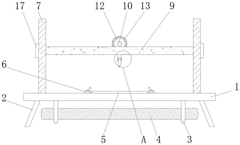
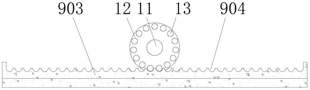
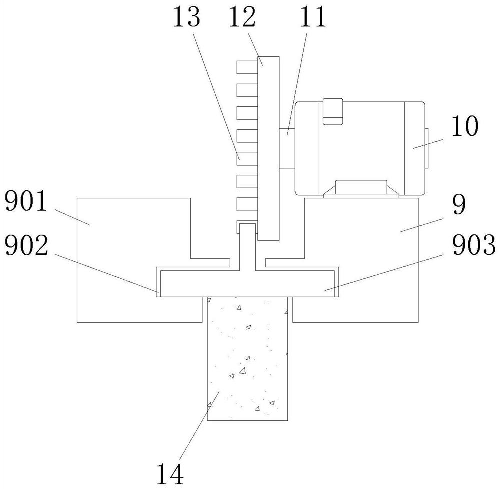
[0029] see Figure 1-7 , a welding device for electrical engineering, comprising a support plate 1, the bottom of the support plate 1 is fixedly connected with support rods 2, the number of support rods 2 is four, and every two support rods 2 form a group, and two groups of support rods The angle between the rod 2 and the horizontal plane is 70 degrees, the bottom of the support plate 1 is fixedly connected to the frame 3, the top of the frame 3 is fixedly con...


PUM


Abstract

The invention relates to the technical field of electrical engineering, and discloses a welding device for electrical engineering. The welding device comprises a supporting plate. Supporting rods are fixedly connected to the bottom of the supporting plate, frames are fixedly connected to the bottom of the supporting plate, and a balancing weight is fixedly connected to the tops of the frames. A silicone rubber pad is arranged at the top of the supporting plate, clamping mechanisms are fixedly installed at the top of the supporting plate, and portal frames are fixedly connected to the top of the supporting plate. Electric push rods are fixedly connected to the inner top walls of the portal frames, a supporting mechanism is fixedly installed at the output ends of the electric push rods, and the supporting mechanism comprises a cross beam. Through the arrangement of the portal frames, the electric push rods and limiting mechanisms, the cross beam can be pushed or pulled up more quickly. Meanwhile, through the arrangement of the two portal frames, the electric push rods and the limiting mechanisms, the situation that the cross beam inclines due to the self-weight of the cross beam during welding work can be avoided, and use is safe and reliable.

Description

technical field [0001] The invention relates to the technical field of electrical engineering, in particular to a welding device for electrical engineering. Background technique [0002] Electrical engineering, referred to as EE, is the core and key discipline in the field of modern science and technology. The traditional definition of electrical engineering is the sum of related disciplines used to create electrical and electronic systems. This definition is very broad, but with the rapid development of science and technology The concept of electrical engineering in the 21st century has gone far beyond the scope of the above definition. A professor at Stanford University pointed out: Today's electrical engineering covers almost all engineering behaviors related to electronics and photons. The advent of the information age based on computer networks will change the way people live and work. The discipline of electrical engineering in American universities, also known as the...

Claims


Application Information

Patent Timeline
Patent Type & Authority Applications(China)
IPC IPC(8): B23K37/02B23K37/00
CPCB23K37/02B23K37/00
Inventor 姚宇龙
Owner 姚宇龙
Why Eureka
Try Eureka