Fuel magnetization treatment method

Inactive Publication Date: 2014-07-24
ZHENJIANG KEYUE ENE TECH
View PDF4 Cites 8 Cited by
  • Summary
  • Abstract
  • Description
  • Claims
  • Application Information

AI Technical Summary

Benefits of technology

[0030]In order to overcome the shortcomings of incomplete combustion of modern engines, this invention provides an ideal process that could significantly increase the combustion ratio of fuels, this process can also increase the output power and torque by increasing the combustion ratio of fuel. For gasoline engines, the complete combustion can con

Problems solved by technology

Although the above technologies have been improved a lot, there still a technical bottle-neck that they cannot really perfectly solve the incomplete combustion fuels in every “power-stroke”, the current technologies can only process the harmful combustible fuel residues by burning them of oxidize them.
All these methods are costly and cannot prevent the wastage of fuels.
We also need to know that the incomplete combustion produce the most harmful emissions to and force us to ‘clean them’ costly.
The PM causes bad health effects, including to respiratory disease and cancers.
As a result of our long term studies, we found that there was a root cause of this incomplete combustion.
. . if we deposit the static potential too much, it will be very dangerous when the static electric discharged at very high voltage.
Furthermore, organic fuels that refined from the oil do not only have single contents, it is a complicated mixture of certain kinds of organic contents and sometime contents water molecules.
Thus, despite the most advanced fuel inj

Method used


Image

  • Fuel magnetization treatment method
  • Fuel magnetization treatment method
  • Fuel magnetization treatment method

Examples


embodiment 1

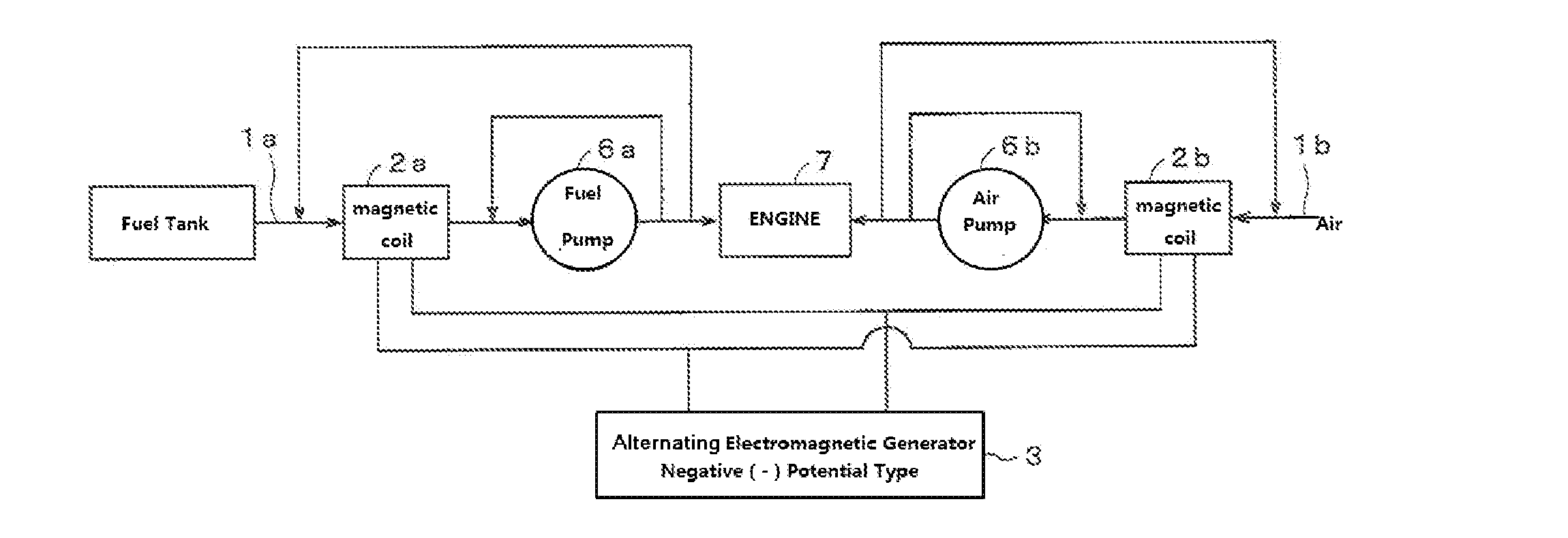
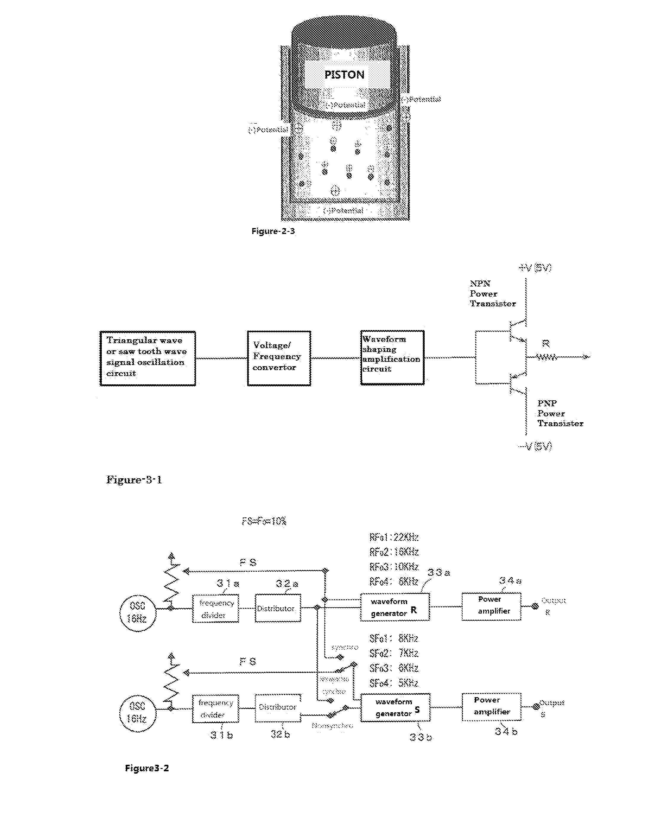
[0140]Table 1 is exhaust gas analysis changes of an engine which has been installed a coil (2a) on the fuel supply pipe (1a) and a Ceramics Coil module (2b) on the air supply pipe (1b). And a Generator Unit (3) which has the circuit of FIG. 3-1 or FIG. 3-2 outputs the special AC current signals to the coils 2a and 2b. The AC current signals are:[0141](a) AC current with a single main frequency, this invention system can be in accordance with the needs of the peak frequency range between 4000 Hz to 25000 Hz one or more output waveform signal;[0142](b) AC currents with different single frequencies mixed together. This invention can be in accordance with the needs of the peak frequency range between 4000 Hz to 25000 Hz a one or more of the output waveform signal;[0143](c) AC current(s) as shown in FIG. 6 having a time-variation frequency band between 4000 Hz to 25000 Hz;

[0144]The embodiment is tested on Japanese Kawasaki Corporation 750 cc motorcycle under the following conditions: our...

embodiment 2

[0149]To install a electromagnetic coil (2a) on the fuel supply pipe (1a) and a electromagnetic coil (2b) on the air supply pipe (1b), wherein the electromagnetic coil (2b) is a electromagnetic coil module with a ceramic layer. And a Generator Unit (3) which has the circuit of FIG. 3-1 or FIG. 3-2 outputs the special AC current signals to the coils 2a and 2b. The use the AC magnetic field generated by the coils (2a and 2b) to magnetize the fuel and air. When switched the generator off, we consider the treatment status as No-Treatment. The calculation method of output power is

W(Watt)=I(current) and V(voltage) that the generator could output

[0150]The AC currents have been shown in FIG. 6 which have time-variation frequency band between 4000 Hz to 25000 Hz. The AC current signals are:[0151](1) AC current with a single main frequency[0152](2) AC currents with different single frequencies mixed together.

[0153](3) AC current(s) having time-variation frequency

[0154]Test conditions and meth...

embodiment-3

[0174]See FIG. 10, it is a cross section of an Air filter housing of a motor car. In a engine system shown in FIG. 1, FIG. 10 was the cross section of the Air Filter (10) that supply clean air to the engine (7). We installed an Ag-coated stainless steel honeycomb-mesh (12) on the air filter element (11), the Ag-mesh could be installed upper or lower of filter element. This metal mesh (12) is also the Ag-mesh used in table-9, table-10 (referred as ‘Ag-mesh). An additional structure of this metal mesh could be a reticular structure module, and bind ceramic balls array (so-called ‘Ion Techno Ball’, with 5 mm diameter, made by Furuya Research) between 2 layers of stainless steel mesh. The density of the ceramics balls array is every 10 mm×10 mm. This metal mesh with ceramic balls were used in the test of Table 9, table 10 (referred ‘Ceramic-mesh’). During the tests, we used the Generator Unit (3) to output special AC currents to Electromagnetic Coil (2b). This coil (2b) could be install...


PUM


Abstract

A fuel magnetization treatment method includes mounting electromagnetic coils on a supply system through which fuel is supplied to a combustion device of an engine (7), connecting two joints of the electromagnetic coils with an electromagnetic generating device, and providing alternating current to the electromagnetic coils through the electromagnetic generating device so that an alternating current magnetic field is generated by the electromagnetic coils and is used to magnetize the fuel in the engine, where the frequency zone of the alternating current is 4 kHz˜25 kHz. The method can improve the combustion efficiency of various fuels, enhance the power output performance of the engine, inhibit the emission of various pollution gases and prolong the life of engine lubricating oil.

Description

TECHNICAL FIELD[0001]This invention is related to the fuel processing technology, in particularly a magnetic processing method for fuels.BACKGROUND[0002]The current typical technical theory of e.g. a four-stroke engine has four strokes in every combusting cycle.[0003]1. INTAKE stroke: The piston descends from the top of the cylinder to the bottom of the cylinder→A mixture of fuel and air, (Or just air in a diesel engine), is forced by atmospheric (or greater) pressure into the cylinder through the intake port→The intake valve(s) then closes.[0004]2. COMPRESSION stroke: With both intake and exhaust valves closed→the piston returns to the top-dead-point, compressing the air or fuel-air mixture into the combustion chamber of the cylinder head→The temperature of the air or fuel-air mixture rises by several hundred degrees during the compression stroke.[0005]3. POWER stroke: While the piston is close to top of the cylinder, the compressed air-fuel mixture in a gasoline engine is ignited;...

Claims


Application Information

Patent Timeline
IPC IPC(8): F02M27/04
CPCF02M27/04C10G32/02F02M27/02F02M2027/047
Inventor HASEGAWA, MANABUFUKAMACHI, SHINPEI
Owner ZHENJIANG KEYUE ENE TECH
Why Eureka
Try Eureka