
Flow Rate Control Device of Hydraulic Pump in Power Steering System

a technology of flow rate control and hydraulic pump, which is applied in the direction of fluid couplings, liquid fuel engines, couplings, etc., can solve the problems of deteriorating fuel ratio of engines, increasing manufacturing costs, and deteriorating handling stability of vehicles, so as to reduce the weight of vehicles, automatic decrease of flow rate and pressure of oil, the effect of improving the handling stability of the steering handl

Inactive Publication Date: 2010-06-24
HYUNDAI MOTOR CO LTD
View PDF5 Cites 15 Cited by
  • Summary
  • Abstract
  • Description
  • Claims
  • Application Information

AI Technical Summary

Benefits of technology

[0011]Various aspects of the present invention are directed to provide a flow rate control device of a hydraulic pump in a power steering device in which a vehicle is driven at high speed, such that a rotation speed of an engine increases and thus the hydraulic pump is operated at high speed, whereby oil pressure and flow rate discharged from the hydraulic pump increase, as a result, handling assisting power of the steering handle increase and when handling stability deteriorates, thereby improving the handling stability of the steering handle by properly decreasing the oil pressure and the flow rate discharged from the hydraulic pump to reduce the handling assisting power of the steering handle, and decreasing a weight and manufacturing cost of a vehicle by a simple structure.
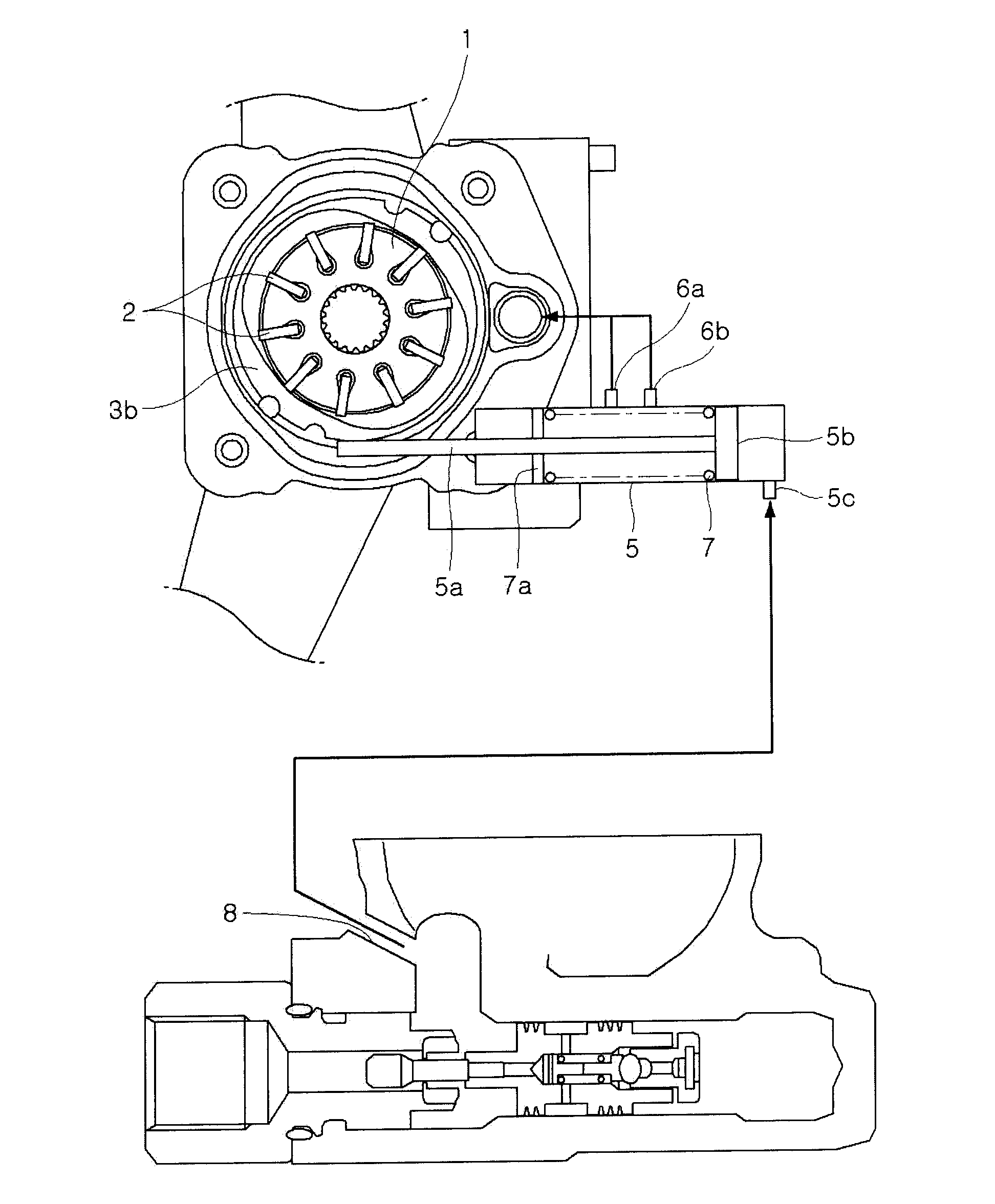
[0018]In a flow rate control device of a hydraulic pump in a power steering system according to various aspects of the present invention, as the vehicle is driven at high speed and the rotation speed of the engine increases, the rotation speed of the hydraulic pump also increases, and thus a flow rate and oil pressure discharged from the hydraulic pump increases. At this time, a part of the flow rate discharged from the hydraulic pump is feed-backed, such that a hydraulic piston is actuated, thereby rotating a cam ring. As the cam ring rotates, a cam profile of the cam ring is changed and an oil pressing space between a rotor and the cam ring is reduced, thereby automatically decreasing a flow rate and pressure of oil generated by changing a volume in the oil pressing space. As a result, the oil pressure and the flow rate of oil discharged from the hydraulic pump and supplied to the power steering system automatically decrease, such that handling assisting power of a steering handle is reduced, thereby improving the handling stability of the steering handle. Further, the temperature of operation oil of the hydraulic pump of the power steering system decreases and thus it is not necessary to install an additional oil cooler, thereby decreasing a weight of the vehicle and saving the manufacturing cost of vehicle. It is possible to improve a layout by reducing a length and a diameter of an oil return hose that guides the oil to the hydraulic pump and it is possible to save development cost and shorten a development period by properly adjusting the rigidity of a spring that flexibly supports the hydraulic piston to facilitate tuning of the hydraulic pump. Therefore, it is possible to reduce the weight of the vehicle, save the manufacturing cost, and improve NVH performance by a simpler structure than the variable capacity type hydraulic pump, and to improve fuel ratio by enhancing deterioration of the fuel ratio of the engine, which is caused due to driving of the hydraulic pump.

Problems solved by technology

However, the hydraulic pump is connected to the engine to be driven by receiving the rotation force of the engine, such that a fuel ratio of the engine is deteriorated.
As a result, a handling feeling of the steering handle becomes lighter, such that the handling stability of the vehicle deteriorates.
In order to solve the above-described disadvantage, the deterioration of the fuel ratio may be improved by adopting a variable capacity type hydraulic pump having a structure in which a cam moves by the internal pressure of the hydraulic pump, but in this case, manufacturing cost increases and the NVH performance of the vehicle deteriorates due to a complicated structure.

Method used


Image

  • Flow Rate Control Device of Hydraulic Pump in Power Steering System
  • Flow Rate Control Device of Hydraulic Pump in Power Steering System
  • Flow Rate Control Device of Hydraulic Pump in Power Steering System

Examples


Embodiment Construction

[0026]Reference will now be made in detail to various embodiments of the present invention(s), examples of which are illustrated in the accompanying drawings and described below. While the invention(s) will be described in conjunction with exemplary embodiments, it will be understood that present description is not intended to limit the invention(s) to those exemplary embodiments. On the contrary, the invention(s) is / are intended to cover not only the exemplary embodiments, but also various alternatives, modifications, equivalents and other embodiments, which may be included within the spirit and scope of the invention as defined by the appended claims.

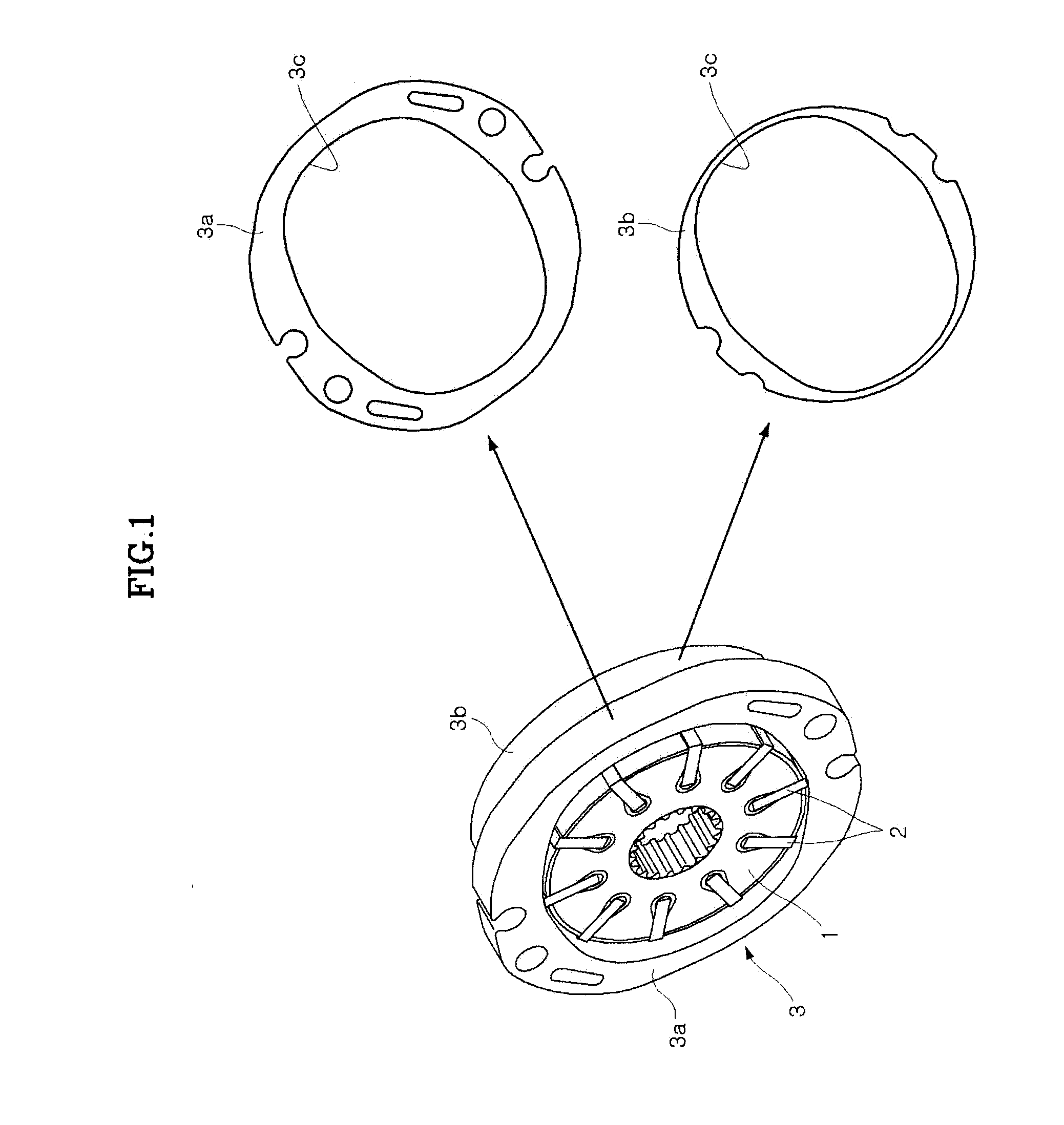
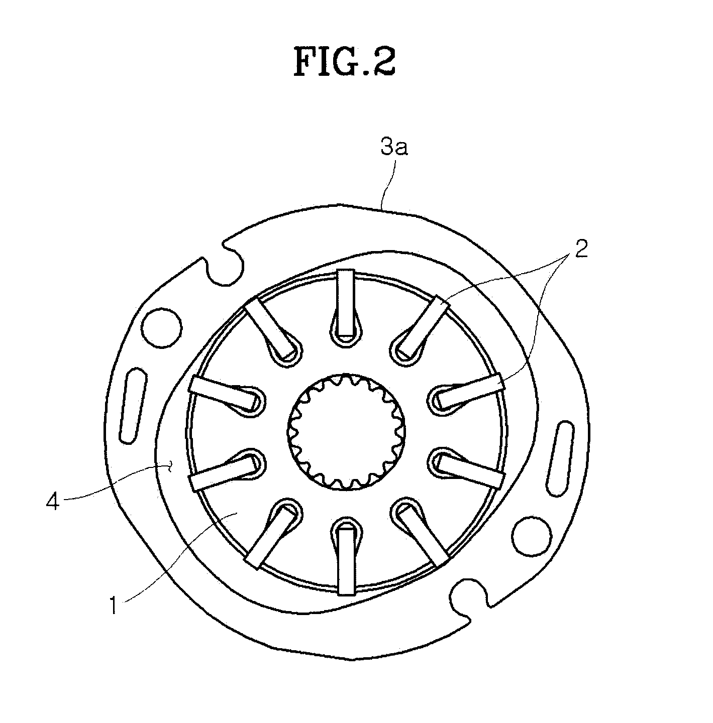
[0027]FIG. 1 is a perspective view of main components of a hydraulic pump in a power steering system according to an exemplary embodiment of the present invention. That is, a plurality of veins 2 are inserted in a circular rotor 1 that is rotatably installed by receiving rotation force of an engine at a predetermined interval in a cir...


PUM


Abstract

A flow rate control device of a hydraulic pump in a power steering system, may include an upper cam ring having a cam profile, which is fixedly installed, a lower cam ring having a cam profile, which is engaged with the upper cam ring to be relatively rotatable about the upper cam ring, and a rotor including a plurality of veins and engaged with the upper and lower cam rings to form an inner space therebetween to pressurize oil by protruding the veins in the inner space by centrifugal force while rotating.

Description

CROSS-REFERENCE TO RELATED APPLICATIONS[0001]The present application claims priority to Korean Application Serial Number 10-2008-0088589, filed on Sep. 9, 2008, the entire contents of which is incorporated herein for all purposes by this reference.BACKGROUND OF THE INVENTION[0002]1. Field of the Invention[0003]The present invention relates to a hydraulic pump in a power steering system, and more particularly, to a flow rate control device of a hydraulic pump in a power steering system, which can improve handling stability of a vehicle by reducing a flow rate discharged from the hydraulic pump when the vehicle is driven at high speed.[0004]2. Description of Related Art[0005]A known power steering system of a vehicle is a system that assists driver's handling force of a steering handle by using oil pressure. The oil pressure is generated by a flow rate discharged from a hydraulic pump.[0006]A rotor having a plurality of centrifugal veins is rotatably installed in a cam ring that is fi...

Claims


Application Information

Patent Timeline
Patent Type & Authority Applications(United States)
IPC IPC(8): B62D5/065F04C2/344
CPCB62D5/0433B62D5/065F01C21/0836F04C2240/30F04C2/3446F04C14/20F04C2240/10F01C21/106B62D5/07B62D5/06
Inventor CHO, SEUNGBUM
Owner HYUNDAI MOTOR CO LTD
Learn More